operation
25
Synrad Firestar f-Series operator’s manual
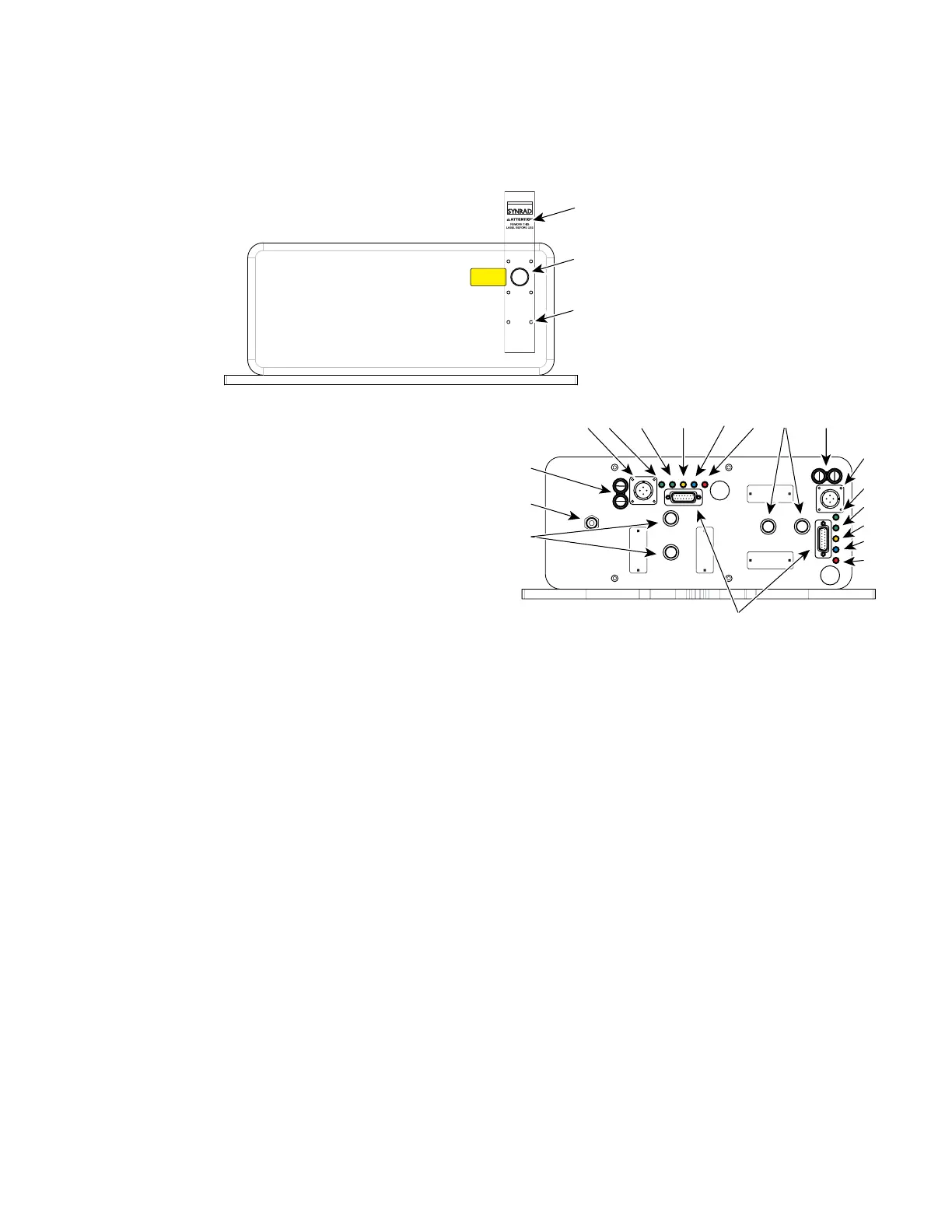
Controls and indicators
Figure 2-4 Firestar f400 controls and indicators
10
Temp Indicator – illuminates green to indicate that coolant temperature and ow is within limits and
that lasing may be enabled. The Temp indicator is red and lasing is disabled if the coolant tempera-
ture rises above safe operating limits.
11
Ready Indicator – illuminates yellow when the laser is enabled, indicating that, after a ve-second
delay, lasing will begin when a PWM Command signal is applied.
12
Shutter Indicator – illuminates blue to indicate that the manual Shutter Switch (if equipped) is Open
and a Shutter Open Request input is connected to the User I/O port so that lasing may be enabled.
When the Shutter indicator illuminates, there is a ve-second delay until PWM inputs are recog-
nized.
13
Lase Indicator – illuminates red to indicate that the laser is actively lasing. The Lase indicator is o
when tickle pulses are being generated and illuminates red when PWM Command signal pulses are
long enough to produce laser output.
14
Keyswitch (Keyswitch models only) – enables/disables operation of the laser. Firestar is enabled when
the Keyswitch is turned to the ON position. Turn the Keyswitch OFF to disable lasing.
15
User I/O Connector – provides a connection point for auxiliary output power, as well as input and
output signals. Refer to User I/O connections in the Technical Reference chapter for pinouts and
signal descriptions.
16
Gas Purge Connector (f400 only) – provides a low pressure nitrogen (or pure air) purge gas connec-
tion to prevent dust and debris from entering the laser housing and damaging electronic or optical
components.
AVOID EXPOSURE
Invisible laser radiation
is emitted from
this aperture.
2
3
Lase Shutter Ready Temp
Remote
Interlock
FUSE
USER I/O
WATER OUT
WATER IN
20A FAST
DC POWER
96 VDC 36A MAX
Lase Shutter Ready Temp
Remote
Interlock
FUSE
USER I/O
WATER OUT
WATER IN
20A FAST
DC POWER
96 VDC 36A MAX
GAS PURGE
Clean and dry
air or N2 only
7
6
8
11
9
 Loading...
