getting started
118
Synrad Firestar f-Series operator’s manual
Caution
possible
equipment
damage
Do not remove or replace the threaded coolant ttings on the rear of
the laser. This can lead to internal leaks, and in some cases, misalign-
ment of the laser. To convert the standard tubing ttings to metric,
please use the 1/2-inch to 12-mm tubing adaptors supplied in the
laser’s ship kit.
Caution
possible
equipment
damage
Inlet cooling water temperature must always be maintained above the
dew point to prevent condensation and water damage to your Firestar
laser.
Connecting
f100/f201 cooling tubing connections
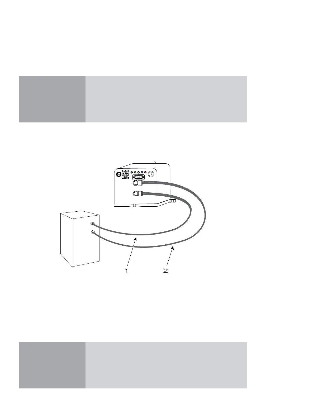
To connect cooling tubing to your f100 or f201 laser, refer to Figure 1-12 and perform the following steps.
The numbered items in Figure 1-12 correspond to the step numbers in the following procedure.
Figure 1-12 Firestar f100/f201 cooling connections
1
Cut and connect a length of cooling tubing to t between the chiller’s Outlet port and the
WATER IN port on the rear of your f100/f201 laser.
2
Cut and connect a length of cooling tubing to t between the WATER OUT port on the rear of the
laser and the chiller’s Inlet port.
OUTLET
INLET
Chiller
WATER IN
WATER OUT
USER I/O
DC POWER
96 VDC 18A MAX
20A FAST
FUSE
ON
OFF/RESET
Lase
Shutter
Ready
Temp
Remote
Interlock
 Loading...
