getting started
112
Synrad Firestar f-Series operator’s manual
Mounting
f201/f400 mounting
Firestar f201/f400 mounting brackets are threaded to accept either metric or standard fasteners.
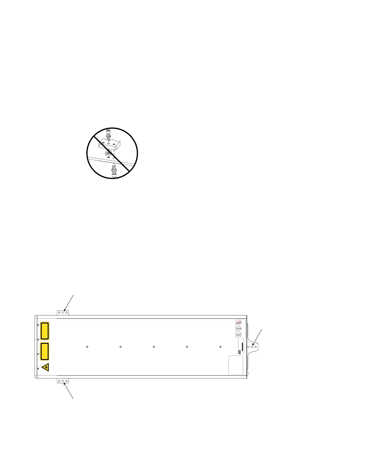
Important Note: As shown in Figure 1-7, DO NOT use more than one fastener per mounting loca-
tion. Using two or more fasteners per mounting tab will cause damage to the laser;
use only one fastener per location to mount your f201/f400 laser.
Figure 1-7 Improper mounting method
Fastening f201/f400 lasers from above
To fasten your f201/f400 laser to a mounting surface from above, perform the following steps:
1
Refer to the appropriate outline and mounting drawing for dimensions and then drill and tap three
M8 × 1.25 (f201) or M10 × 1.5 (f400) holes into your mounting surface. For SAE installations, drill
and tap three 5/16–18 (f201) or 3/8–16 (f400) holes into your mounting surface.
These hole locations (referenced by Note 2 on the O & M drawings) should correspond to the thru
holes labeled “A” as shown in Figure 1-8.
Figure 1-8 Fastening f201/f400 from above
2
Assemble three spherical washer sets as detailed in the Outline and Mounting drawing.
3
Place the spherical washer sets over the threaded holes in your mounting surface.
Do not use more than
one fastener per mount
ing foot. Doing so will
damage the laser
INVISIBLE LASER RADI A TIO N
A V OID EYE OR SKIN EXPOSURE T O
DIRECT OR SC A TTERED RADI A TIO N
CLASS 4 LASER P R ODUC T
EN-60825-1, 2007
1400 W A TTS MA X
10200-10800 NANOMETERS
C A UTION
CONDENS A TION AN D
W A TER D AM A GE CA N
OCCUR IF COOLING W A TE R
IS BEL O W DEW POIN T .
SEE OPER A TION MAN U AL .
Insert metric or UNC
fastener thru laser
mount and spherical
washer set into threaded
mounting plate
Insert metric or UNC
fastener thru mounting
plate and spherical washer
set into threaded metric
or UNC hole in laser mount
Do not use more than
one fastener per mount-
ing foot. Doing so will
damage the laser
OR
The RF Drive circuit in this laser is designed to
sense fault conditions that could potentially
damage the laser’s electronic circuit boards.
On rare occasions, the laser may shutdown during
the start-up sequence. When this happens, the
Ready indicator will flash a series of three blinks,
pause, and then repeat. If this occurs, remove DC
power from the laser, wait 30 seconds, and then
re-apply DC power.
If the Ready indicator continues to flash, contact
SYNRAD, Inc. as this may indicate a serious
problem in the laser’s control circuit.
MODEL #: FSF400SD
SERIAL #: F400204082943
TESTED AT: 96V MFG: July 22, 2008
This laser component does not comply with standards for complete
laser products as specified by 21 CFR 1040.10 or IEC 60825-1.
SYNRAD, Inc. 4600 Campus Place, Mukilteo WA 98275 425.349.3500
Top View
(f400 model shown)
Cooling fittings
removed for clarity
 Loading...
