technical reference
313
Synrad Firestar f-Series operator’s manual
User I/O connections
Input/output signals
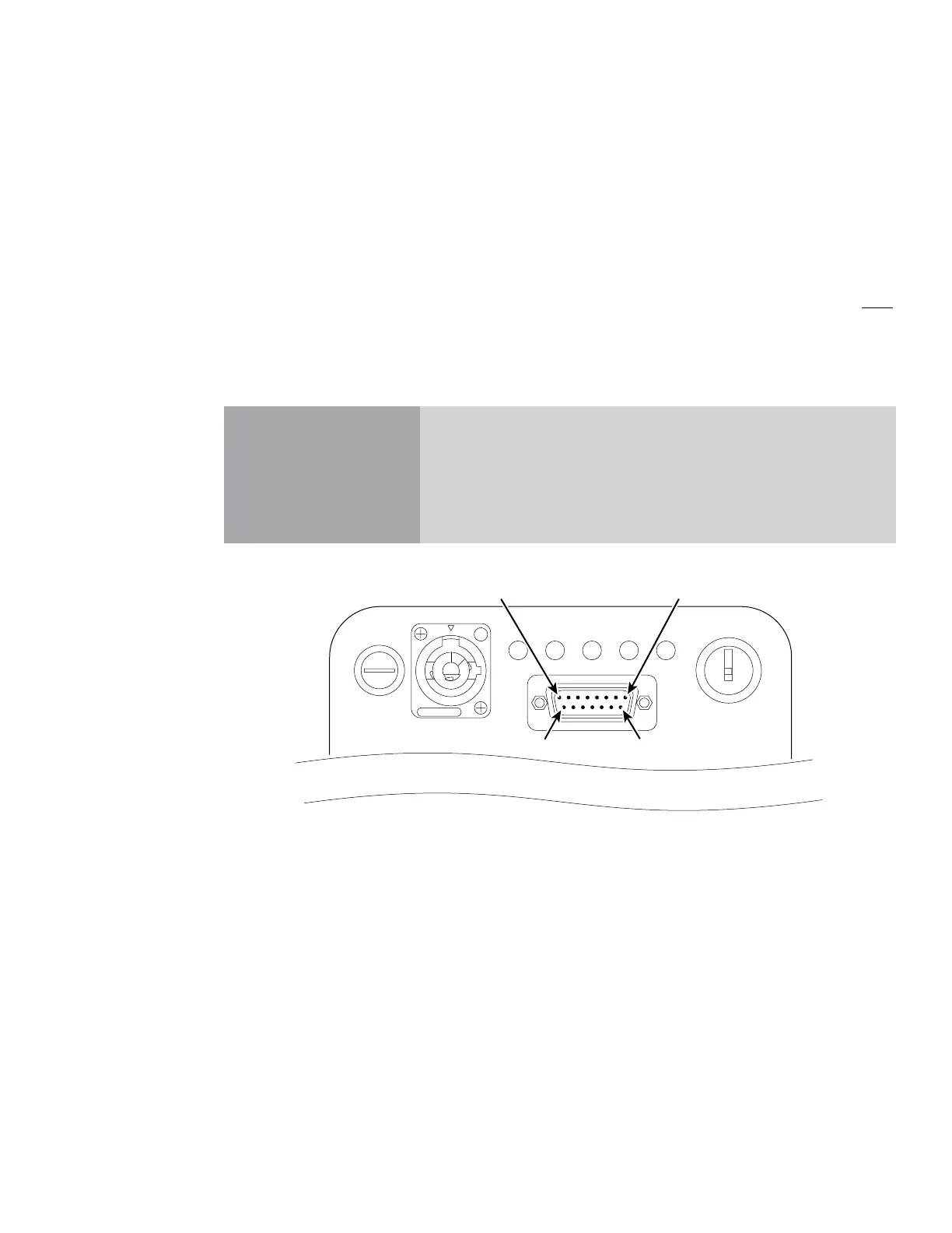
Firestar’s input/output signals are divided into three categories: auxiliary DC power, input signals, and out-
put signals. Signals in each category are fully described in the sections below. Figure 3-5 illustrates the pin
arrangement of the User I/O (15 pin female D-type subminiature) connector on Firestar’s rear panel.
Important Note: Because Firestar f200/f400 lasers are dual-tube lasers, all control connections (inputs,
outputs, and PWM Command signals) must be connected in parallel between both
User I/O connectors. This assures that both tubes are driven equally and that input
and output control signals are able to enable or disable both laser tubes simultane-
ously. See Figure 3-17 later in this section for an example circuit.
Caution
possible
equipment
damage
Turn o DC power before installing or removing any plug or cable
from the User I/O connector. Ensure that user connections are made
to the appropriate pins and that the appropriate signal levels are ap-
plied. Failure to do so may damage the laser.
Figure 3-5 User I/O connector pinouts
USER I/O
DC POWER
96 VDC 18A MAX
20A FAST
FUSE
ON
OFF/RESET
LaseShutterReadyTemp
Remote
Interlock
Pin 9Pin 15
 Loading...
