technical reference
37
Synrad Firestar f-Series operator’s manual
Controlling laser power
Warning
serious
personal
injury
Always use shielded cable when connecting your PWM Command
signal source to PWM Input/PWM Return inputs. In electrically-
noisy environments, long lengths of unshielded wire act like an
antenna and may generate enough voltage to trigger uncommanded
lasing.
T
T
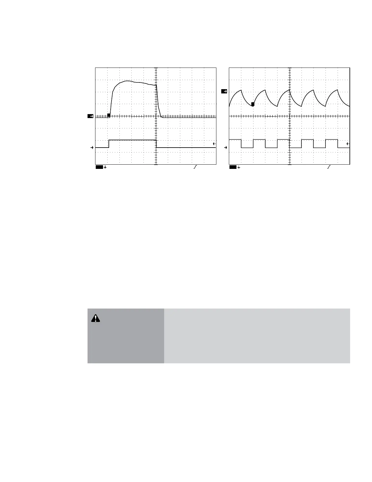
100mV Ch2 5 V M 250µs Ch2 1.6 V
Ch1
Optical output pulse (10% duty cycle at 100 Hz)
22
1
T
50mV Ch2 5 V M 100µs Ch2 1 V
Ch1
Optical output pulse (50% duty cycle at 5 kHz)
T
Figure 3-3 Typical Firestar f-Series waveforms
Firestar f-Series lasers are designed to operate at Command signal base frequencies up to 100 kHz; how-
ever, the choice of PWM frequency depends on the user’s specic application. In the majority of laser
applications, the UC-2000’s default Command signal frequency of 5 kHz has proven to work well. When
considering Command frequencies at 5 kHz or below, please review Marking/engraving operation later in this
section. For high-speed motion applications that cannot tolerate any ripple in the optical beam response
but still need adjustable power levels, we recommend the use of higher PWM frequencies, up to 100 kHz
maximum. At 100 kHz, the laser’s optical beam response no longer follows the Command input and is very
nearly a DC value with just a small amount of ripple present.
Command signal
The modulated Command signal applied between Pin 9, PWM Input, and Pin 1, PWM Return, of the User
I/O connector on the Firestar f-Series laser has three basic parameters: signal amplitude, base frequency,
and PWM duty cycle. By changing these parameters, you can command the beam to perform a variety of
marking, cutting, welding, or drilling operations.
The rst Command signal parameter, signal amplitude, is either logic low—corresponding to laser beam
o, or logic high—corresponding to beam on. The laser o voltage, typically 0 V, can range from 0.0 V to
+0.8 VDC while the laser on voltage, typically 5 V, can range from +3.5 V to +6.7 VDC.
Base frequency, the second parameter, is the repetition rate of the PWM input signal. The standard base
frequency is 5 kHz, which has a period of 200 µs. Maximum PWM frequency is 100 kHz.
 Loading...
