operation
22
Synrad Firestar f-Series operator’s manual
Controls and indicators
The Controls and indicators section includes subsections:
■ f100/f201 lasers
■ f200/f400 lasers
f100/f201 lasers
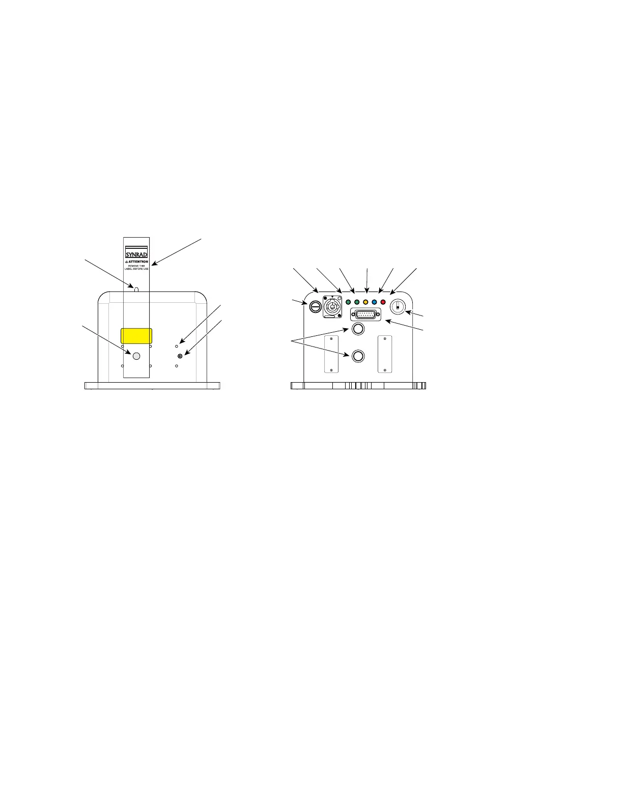
Figure 2-1 Firestar f100 controls and indicators
1
Shutter Switch (f100 only) – activates a mechanical shutter that opens or closes the laser aperture.
Closing the shutter also interrupts RF power to the laser. There is a ve-second delay imposed from
the time the shutter is opened to the time that PWM Command signals are accepted.
2
Laser Aperture – provides an opening in Firestar’s front panel from which the beam exits.
3
Aperture Seal – prevents dust from damaging the output coupler during shipping. Remove the red
self-adhesive label before applying power to the laser.
4
Optical Accessories Mounting – provides six threaded holes (8–32 UNC) for mounting optional
beam delivery components available from SYNRAD. Because excessive weight may damage the
laser, consult SYNRAD before mounting components not specically designed as Firestar options.
Refer to Firestar package outline drawings in the Technical Reference chapter for mounting dimen-
sions.
Note: When mounting optical components to f-Series lasers, the 8–32 UNC fasteners must extend no
further than 4.8 mm (0.19") into the laser’s faceplate.
5
Diode Pointer Power Connector (f100 only) – provides a convenient +5 VDC, 50 mA receptacle to
power a visible red diode pointer (available from SYNRAD as an optional accessory).
6
WATER OUT and WATER IN Ports – provides connection points for Firestar’s cooling system using
non-removable straight 1/2-inch ttings. A cooling kit contains 90° tubing adaptors for both 1/2-
inch and 12-mm cooling tubing.
7
FUSE Holder – protects laser circuitry with a 20 A, 125 V fast-acting fuse.
AVOID EXPOSURE
Invisible laser radiation
is emitted from
this aperture.
1
4
DC POWER
96 VDC 18A MAX
WATER IN
WATER OUT
USER I/O
20A FAST
FUSE
ON
OFF/RESET
Lase Shutter Ready Temp
Remote
Interlock
 Loading...
