technical reference
324
Synrad Firestar f-Series operator’s manual
User I/O connections
f200/f400 I/O connections
There are two DB-15 User I/O connectors on Firestar f200 and f400 dual-tube lasers (called Set 1 and
Set 2 for convenience). When connecting eld wiring between your control system and an f200 or f400
laser, the three input signals (Remote Reset/Start Request, Remote Interlock, and Shutter Open Re-
quest) as well as the PWM input must be wired in parallel to both Set 1 and Set 2 User I/O connectors.
When monitoring any, or all, of the ve user outputs, you must monitor both Set 1 and Set 2 simultane-
ously as a failure or shutdown of a single tube will result in reduced laser power output.
To supply power to external I/O circuit(s) from Firestar’s +5 VDC Auxiliary Power or +24 VDC Auxiliary
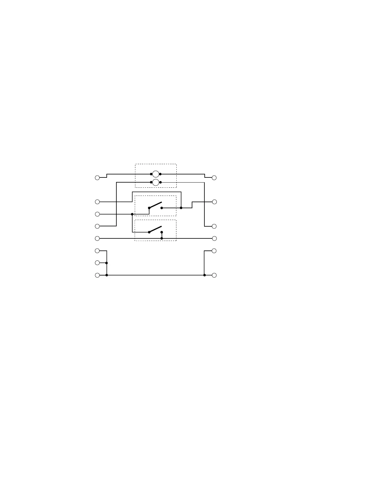
Power outputs, wire the Set 1 and Set 2 User I/O connectors as shown in Figure 3-17 and described below.
Figure 3-17 Wiring Set 1 and Set 2 to power external circuits
1
Set 1 – Connect Pin 5, +24 VDC Auxiliary Power (or Pin 4, +5 VDC Auxiliary Power), to the
external circuit(s) you are powering (total load – 250 mA maximum).
2
Connect Pin 11 (Input Common) to Pin 12 (Aux. DC Power Ground) and Pin 13 (Output Com-
mon).
3
Set 2 – Connect Pin 11 (Input Common) to Pin 13 (Output Common). Leave Pins 4, 5, and 12
open (disconnected).
4
Connect the junction of Pins 11/12/13 from Set 1 to the junction of Pins 11/13 on Set 2.
5
Connect remaining input/output signals as required to the appropriate pins on both the Set 1 and
Set 2 User I/O connectors.
USER I/O PINS
PWM RETURN
REMOTE INTERLOCK
VDC AUXILIARY POWER
PWM INPUT
SHUTTER OPEN REQUEST
(1)
(3)
(5)
(9)
(10)
(11)
(12)
(13)
INPUT COMMON
AUX. DC POWER GROUND
OUTPUT COMMON
USER I/O PINS
PWM RETURN
PWM INPUT
(1)
(9)
(11)
(13)
INPUT COMMON
OUTPUT COMMON
Ext Shutter Circuit
Ext Interlock Circuit
Ext PWM Source
–
+
REMOTE INTERLOCK
(3)
(10)
 Loading...
