getting started
119
Synrad Firestar f-Series operator’s manual
Connecting
3
Turn on the chiller and adjust the temperature setpoint to 18 °C to 22 °C. Regulate coolant ow to
7.6 lpm (2.0 GPM) for f100 or 9.5 lpm (2.5 GPM) for f201 lasers at less than 414 kPa (60 PSI) of
pressure.
4
Closely examine all cooling connections and verify that there are no leaks.
f200/f400 cooling tubing connections
Caution
possible
equipment
damage
Do not remove or replace the threaded coolant ttings on the rear of
the laser. This can lead to internal leaks, and in some cases, misalign-
ment of the laser. To convert the standard tubing tting to metric,
please use the 1/2-inch to 12-mm tubing adaptors supplied in the
laser’s ship kit.
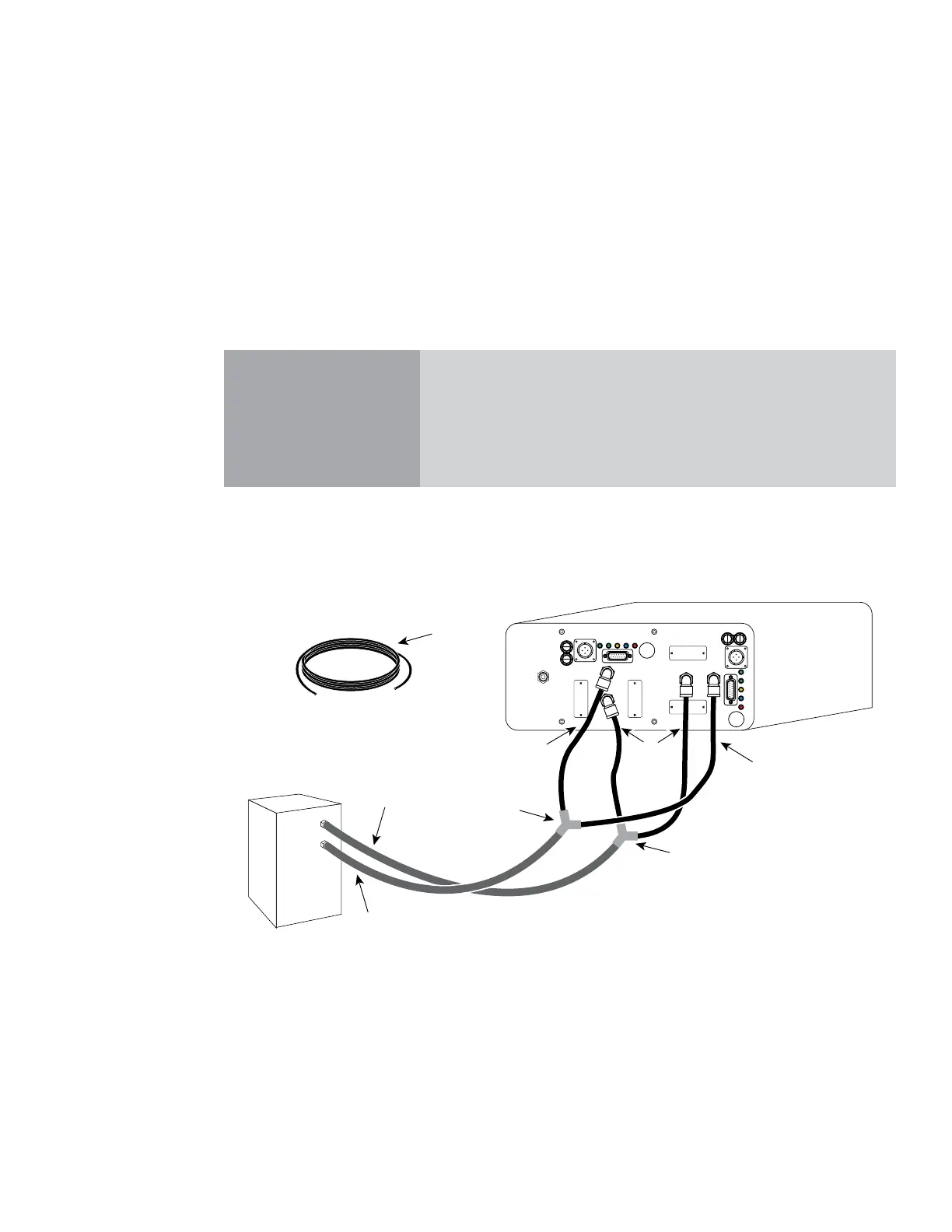
To connect cooling tubing to your f200 or f400 dual-tube laser, refer to Figure 1-13 and perform the follow-
ing steps. The numbered items in Figure 1-13 correspond to the step numbers in the procedure.
Figure 1-13 Firestar f200/f400 cooling connections
1
Locate the 1/2-inch O.D. cooling tubing in the Ship Kit and cut four lengths (12–18 inches long) to
t partway between your chiller and the rear of the Firestar f200/f400 laser.
2
Select two lengths of tubing and connect one end of each piece to the laser’s WATER IN ports.
3
Connect the other end of each length of tubing to the “Y” tting (included in the Ship Kit).
4
Cut and connect a length of tubing to t between the chiller’s Outlet port and the center of the “Y”
tting.
OUTLET
INLET
Chiller
LaseShutterReadyTemp
Remote
Interlock
FUSE
USER I/O
WATER IN
20A FAST
DC POWER
96 VDC 36A MAX
LaseShutterReadyTemp
Remote
Interlock
FUSE
USER I/O
WATER OUT
WATER IN
20A FAST
DC POWER
96 VDC 36A MAX
GAS PURGE
Clean and dry
air or N2 only
WATER OUT
3
2
4
5
5
6
7
1
 Loading...
