technical reference
320
Synrad Firestar f-Series operator’s manual
User I/O connections
Sample I/O circuits
Sample inputs
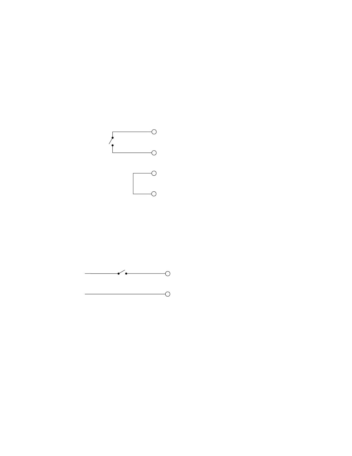
Figure 3-10 illustrates one method of supplying a Remote Interlock signal using a customer-supplied limit
switch. Firestar’s +24 VDC Auxiliary Power output powers the circuit. Note that Pin 4, +5 VDC Auxiliary
Power, could have been used instead, depending on circuit voltage requirements.
(12) AUX. DC POWER
Close switch to
le interlock
(5) +24 VDC AUXILIARY
POWER
(3) REMO
(11) INPUT COMMON
Figure 3-10 Customer-supplied interlock
Figure 3-11 shows another variation for supplying a Remote Interlock signal to the laser. In this case, the
customer is using a limit switch and supplying a negative voltage to drive Firestar’s input circuit.
enable interlock
(3) REMO
TE INTERLOCK
(11) INPUT COMMON
–12
VDC
0 VDC
Figure 3-11 Customer-supplied interlock, negative voltage
 Loading...
