getting started
111
Synrad Firestar f-Series operator’s manual
Mounting
3
Place your Firestar f100/f200 laser on the mounting surface so that mounting areas on the baseplate
line up with the threaded holes in the mounting surface.
4
Insert three M6 × 1 or 1/4–20 capscrews through Firestar’s baseplate into the threaded holes of the
mounting surface. Turn the screws by hand until the threads engage.
5
Evenly tighten all three capscrews to a maximum torque of 6.1 N m (54 in lb).
Fastening f100/f200 lasers from below
To fasten your f100/f200 laser to a mounting surface from below (using 1/4—20 UNC fasteners), perform
the following steps:
1
Refer to the appropriate outline and mounting drawing for dimensions and then drill three 0.257"
(6.5 mm) close t or 0.281" (7.1 mm) normal t holes into your mounting surface. Hole locations
(referenced by Note 2 on the O & M drawings) should correspond to the threaded holes labeled “C”
as shown in Figure 1-6.
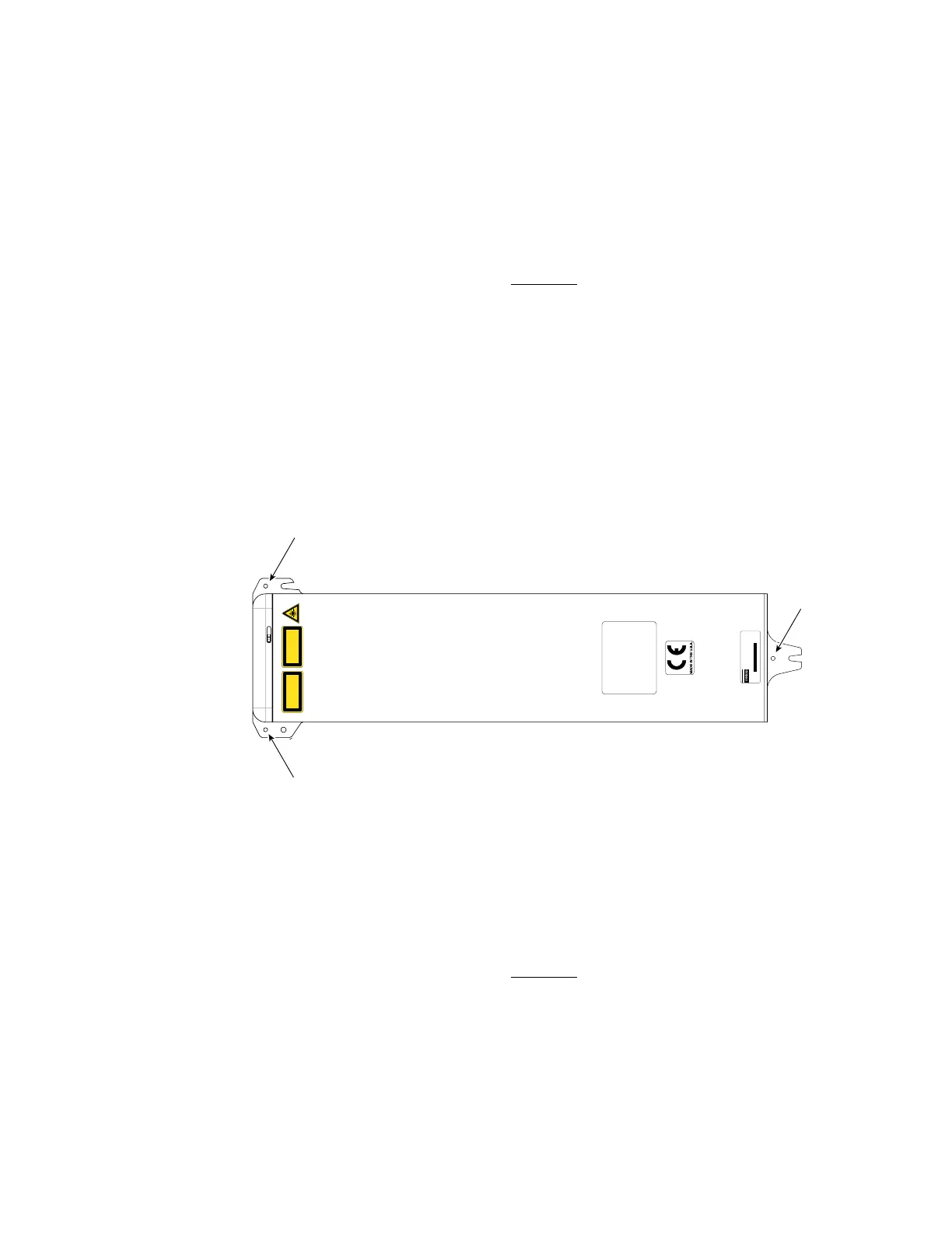
Figure 1-6 Fastening f100/f200 from below
2
Place your Firestar f100/f200 laser on the mounting surface so that the threaded holes on the
baseplate (labeled “C” in Figure 1-6) line up with the holes drilled through the mounting surface.
3
Insert the three 1/4–20 × 3/4" capscrews through the mounting surface into the threaded holes of
Firestar’s baseplate. Turn the screws by hand until the threads engage.
4
Evenly tighten all three capscrews to a maximum torque of 6.1 N m (54 in lb).
CAUTION
CONDENSATION AND
WATER DAMAGE CAN
OCCUR IF COOLING WATER
IS BELOW DEW POINT.
SEE OPERATION MANUAL.
EN-60825-1, 2007
400 WATTS MAX
10200-10800 NANOMETERS
INVISIBLE LASER RADIATION
AVOID EYE OR SKIN EXPOSURE TO
DIRECT OR SCATTERED RADIATION
CLASS 4 LASER PRODUCT
Top View
(f100 model shown)
The RF Drive circuit in this laser is designed to
sense fault conditions that could potentially
damage the laser’s electronic circuit boards.
On rare occasions, the laser may shutdown during
the start-up sequence. When this happens, the
Ready indicator will flash a series of three blinks,
pause, and then repeat. If this occurs, remove DC
power from the laser, wait 30 seconds, and then
re-apply DC power.
If the Ready indicator continues to flash, contact
SYNRAD, Inc. as this may indicate a serious
problem in the laser’s control circuit.
Cooling fittings
removed for clar
C
MODEL #: FSF100SD
SERIAL #: F100204082943
TESTED AT: 96V MFG: July 22, 2008
This laser component does not comply with standards for complete
laser products as specified by 21 CFR 1040.10 or IEC 60825-1.
SYNRAD, Inc. 4600 Campus Place, Mukilteo WA 98275 425.349.3500
 Loading...
