AR 2000 Operator’s Manual
96
8. Install Peltier Jacket on rheometer using Smart Swap Connectors.
9. Install the Magnet Assembly onto the shaft of the rheometer.
10. Rotate the draw rod so the magnet assembly refer-
ence mark is aligned with the small magnet on the
Rotor. Ensure that the reference mark on the upper
geometry remains aligned with the small magnet by
lightly holding the rheometer draw rod and begin
lowering the rheometer head as shown in Figure
8.16
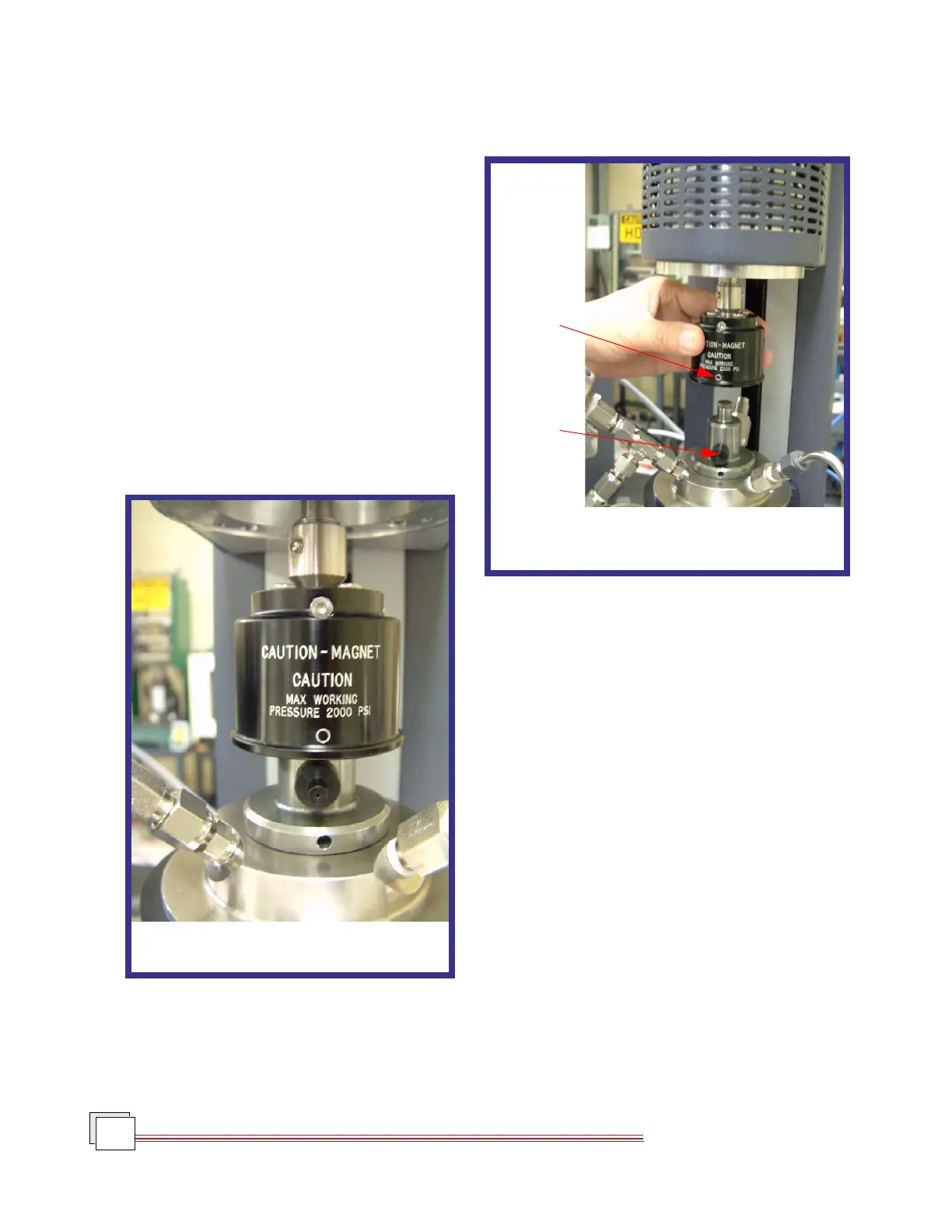
11. At a gap of about 20 mm between the shoulder on
the rotor assembly, and the underside of the upper
magnet assembly, the magnets in the upper assem-
bly will engage with those in the rotor assembly as
shown in Figure 8.17. (A small noise will be heard
when this happens and a change of a few Newtons
will be seen in the normal force reading.). Immedi-
ately stop moving the rotor assembly down and
remove the small magnet.
Figure 8.16
Aligning the Reference Mark
Reference
Mark
Small
Magnet
Figure 8.17
Magnets Engaging