EasyManuals Logo

TA Instruments AR 2000 User Manual

TA Instruments AR 2000
144 pages
To Next Page IconTo Next Page
To Previous Page IconTo Previous Page
Page #99 background imageLoading...
Page #99 background image
AR 2000 Operators Manual
99
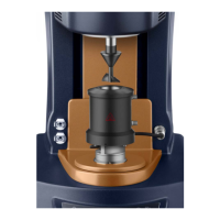
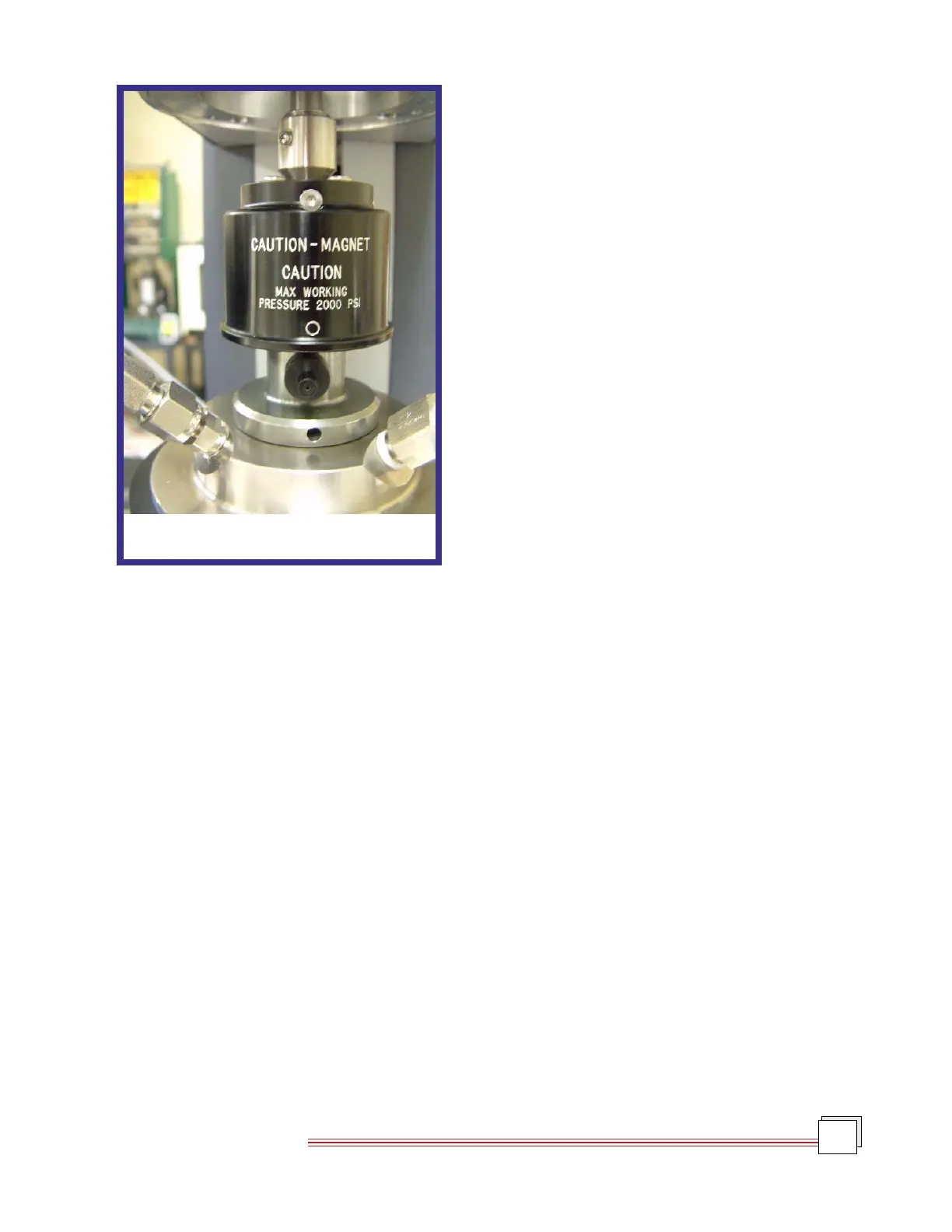
9. At a gap of about 20 mm between the shoulder on the
rotor assembly and the underside of the upper magnet
assembly the magnets in the upper assembly will
engage with those in the rotor assembly as shown in
Figure 8.19. (A small noise will be heard when this
happens and a change of a few Newtons will be seen
in the normal force reading.). Immediately stop mov-
ing the rotor assembly down and remove the small
magnet.
10. Lower the instrument head to the geometry gap
(default 3500 µm). Do not zero the gap.
Figure 8.19
Magnets Engaging

Table of Contents

Questions and Answers:

Question and Answer IconNeed help?

Do you have a question about the TA Instruments AR 2000 and is the answer not in the manual?

TA Instruments AR 2000 Specifications

General IconGeneral
BrandTA Instruments
ModelAR 2000
CategoryMeasuring Instruments
LanguageEnglish

Related product manuals