RSA-G2 Getting Started Guide Page 40
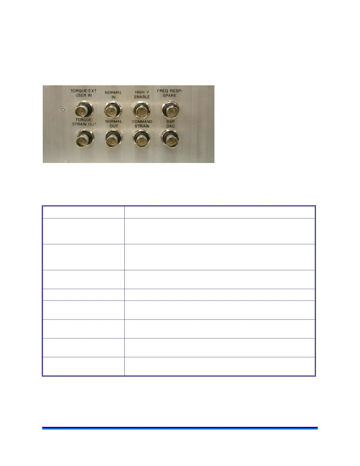
Lower Signal Panel Connections
The lower signal panel labels (shown below) are common between the ARES-G2 and RSA-G2. For the
connections with two labels, the first label is applicable to the ARES-G2 and the second label is applicable
to the RSA-G2.
The figure below identifies the lower set of connections on the ARES-G2/RSA-G2 signal panel.
Figure 22 RSA-G2 lower signal panel.
The table below contains information regarding the RSA-G2 lower signal panel connectors.
Table 6: Lower Signal Panel Connector Descriptions
Connector Purpose
EXT USER IN An external user input that can be connected to the internal strain measure-
ment channel instead of the motor strain signal. (User selectable.)
Input scaling is ±5 VDC
NORMAL IN An external user input that can be connected to the internal normal measure-
ment channel instead of the transducer normal signal. (User selectable.)
Input scaling is ±5 VDC
HIGH V ENABLE A relay contact closure that is used to enable the high voltage amplifier of the
ER Accessory.
SPARE Unused connection.
STRAIN OUT Outputs a DC voltage that is proportional to motor strain.
Scaling is ±5.0 VDC = ± Full Scale Strain
NORMAL OUT Outputs a DC voltage that is proportional to motor strain.
Scaling is ±5.0 VDC = ± Full Scale Force
COMMAND STRAIN Outputs a DC voltage that is proportional to the actual motor defection.
Scaling is ±10.0 VDC = ± Full Scale Command
DSP
DAC
A general purpose ±10-volt analog output for future use that is derived from a
digital-to-analog converter on the DSP board.