3-19
3
TRAVEL MOTOR
FUNCTION
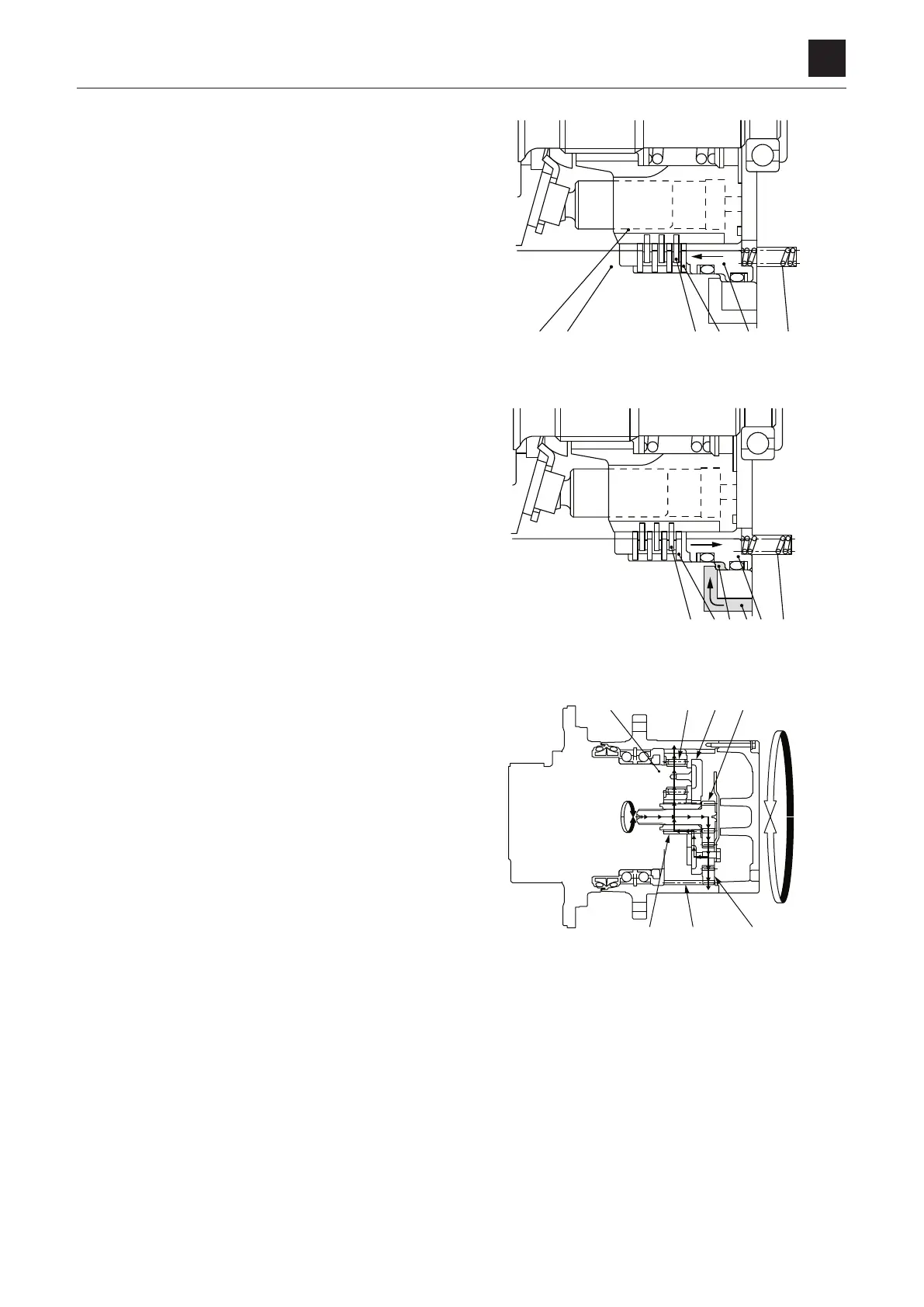
Parking brake
The friction disc (2) and the disc (1) are connected through
the spline. The friction disc (2) and the disc (1) are pressed
against the flange holder (6) by the springs (4) via the brake
piston (5). The friction force between these discs gener-
ates
the brake torque to prevent the cylinder block (3) from
rotating.
When the pressure oil is dorected into the motor, the oil
flows from the parking brake release port (7) into the brake
piston chamber (8). The oil pressure overpowers the spring
force and moves the brake piston (5) to the right. This gen-
erates
a clearance between the friction disc (2) and the disc
(1) to release the parking brake function. Once the motor
stops, no pressure oil flows into the parking brake release
port (7) and the parking brake force is operated by the
spring (4).
Reduction gears
The reduction gears consist of 2-stage simple planetary
gears connected in series. Each planetary gear consists
of a sun (input) gear, an internal tooth ring gear and planet
gears mounted on a carrier. The sun gear “floats” within the
planet gears so as to attain uniform load distribution at the
multiple gear mesh points.
The
motor drives the 1st stage sun gear (1) which in turn
drives the 1st planet gears (2). Since these planet gears (2)
are engaged with the ring gear (3), the rotation is transmit-
ted to the 1st stage carrier (4).
The
1st stage carrier (4) is coupled directly to the 2nd stage
sun gear (5) which in turn drives the 2nd planet gears (6).
The 2nd stage carrier (7) is a part of the motor housing
(non-rotating) and thus the main torque is output to the ring
gear (3). The output flange rotation is opposite to the input
rotation.