3-8
3
CONTROL VALVE
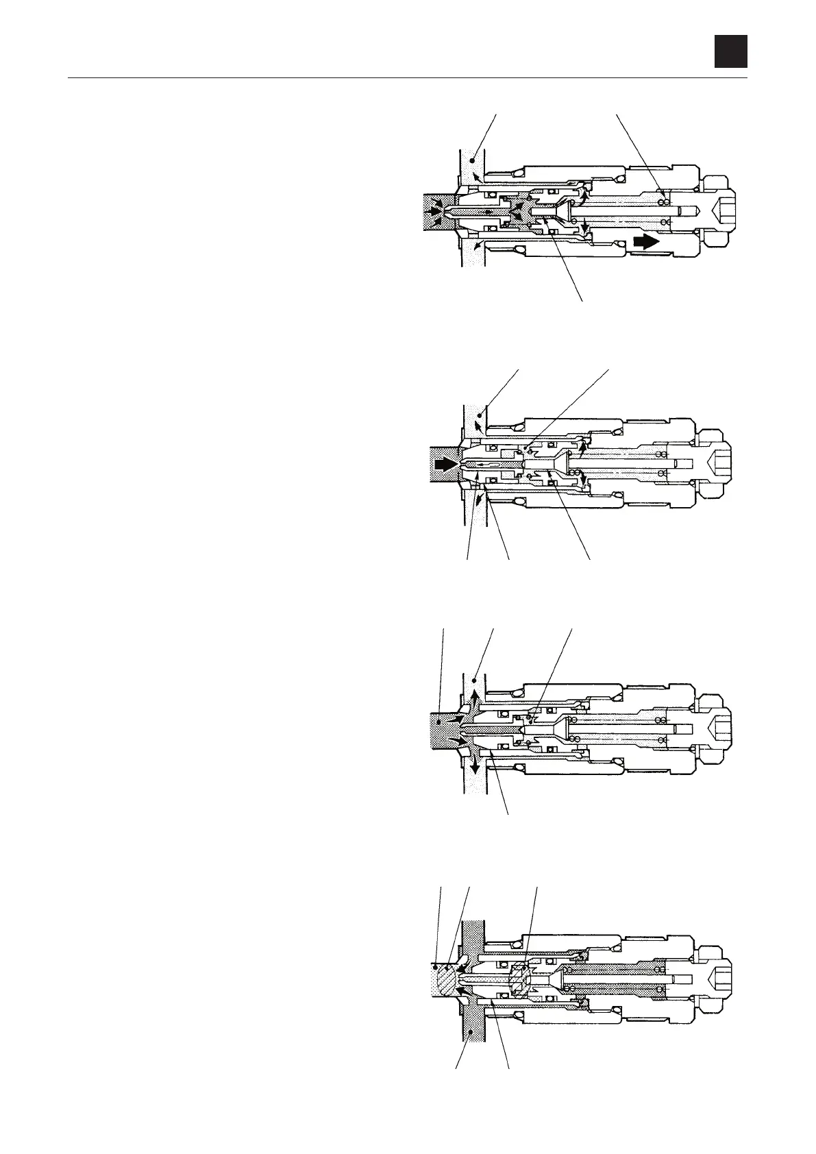
FUNCTION
If the pressure in the circuit becomes higher than the force
of the spring (7), the needle valve (5) is pushed to the right
by hydraulic pressure, connecting the high-pressure area
with the tank passage T. The oil then flows around the cir-
cumfer
ence of the needle valve (5) and passes through the
slits, flowing into the tank passage T.
When the needle valve (5) is pushed to the right to con-
nect
the high-pressure area with the tank passage T, the
pressure on the back side of the piston (4) drops and the
piston (4) is pushed to the right against the needle valve
(5).This shuts off the flow of hydraulic oil flowing from the
chamber B to the chamber C, resulting in a low pressure in
the chamber C.
If
the pressure of the chamber C becomes lower than that
of the chamber B, equilibrium cannot be maintained. As a
result, the main poppet (6) opens to allow the hydraulic oil
to flow into the tank passage T.
Suction operation:
If
the cylinder is operated at a speed too fast for the oil
supply to keep up, and thus the pressure of the chamber B
becomes almost negative, the oil from the tank is supplied
to prevent cavitation.
When the pressure in chamber B is lower than the pressure
in the tank passage T, the difference in the sectional areas
of A and A1 causes the main poppet (6) to open. Then,
oil to fill the space in the chamber B enters from the tank
passage T.