131
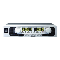
Figure 5–2: LIST Mode Sequence Example
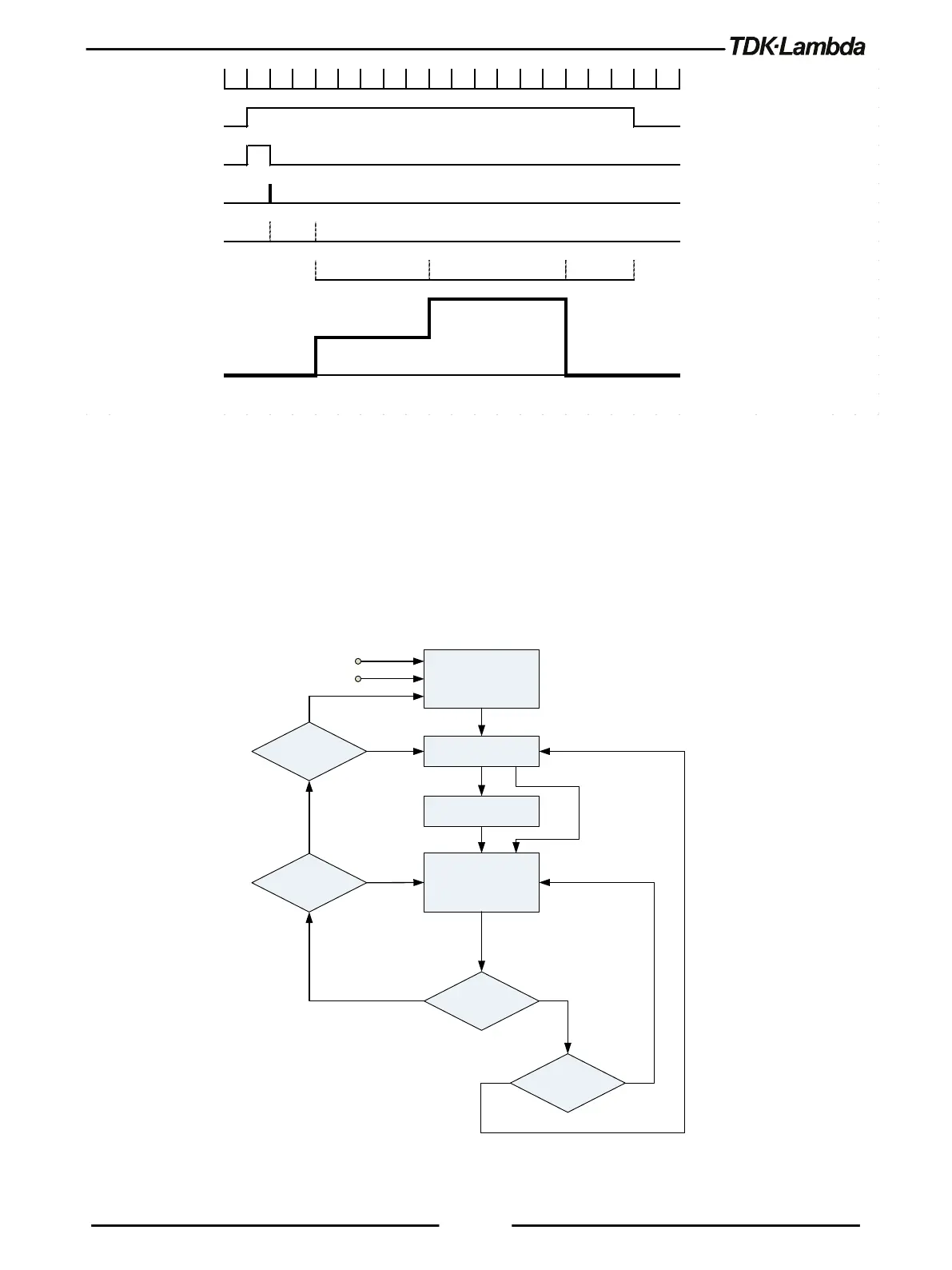
5.1.2 WAVE Mode
Output value change in slopes is determined by parameters in the WAVE. Output change is
activated by the input trigger (refer to section 5.2.2). Program WAVE parameters are activated by
the Program subsystem. For WAVE related commands, refer to section 4.14.7.
Set the operation mode by [SOURce]:CURRent:MODE <DSC> and/or [SOURce]:VOLTage:MODE
<DSC> command/s.
IDLE STATE
INITIATE STATE
DELAY STATE
OUTPUT CHANGE
STATE
(LINEAR STEP)
WAVE STEP
COMPLETE
PROG:STEP
AUTO
PROG:COUN
INIT:CONT
ABORT
*RST
INIT[:IMM]
TRIG[:IMM]
TRIGGERED EVENT
NO
YES
0
>0
YES
YES
NO
NO
Figure 5–3: Simplified WAVE Mode Model
0.01s ec
Trigger Initiated INIT:IMM
Trigger Wait
Trigge r Event
Trigger Delay TRIG:DEL 0.02
Dwell LIST:DWELL 0.05,0.06,0.03
OUTPUT LIST:VOLT 5,10,0