10
11 Isolated control and
Isolated analog Control and monitoring signals, DB26HD type female,
isolated from the output potential.
Position for optional communication interface.
13 Service Port Service port for factory use. USB interface connector, type B. Connector
type: SAMTEC P/N: USBR-B-S-F-O-TH.
Table 1-4: Rear Panel Connections and Controls
NOTE
* LAN Connector LEDs (Green & Amber) and Red Status Indicators might lit in Power Switch OFF
state.
WARNING
Refer to the Safety & Installation Manual for any connect/disconnect of any connector on the rear
panel.
1.6
J1 Connector Terminal and Function
Control and monitoring signals are SELV.
Connector Technical Information:
Connector type: 618026325223, WURTH
DB26HD Receptacle type: 10090769-P264ALF, FCI
Wire: AWG 24-28
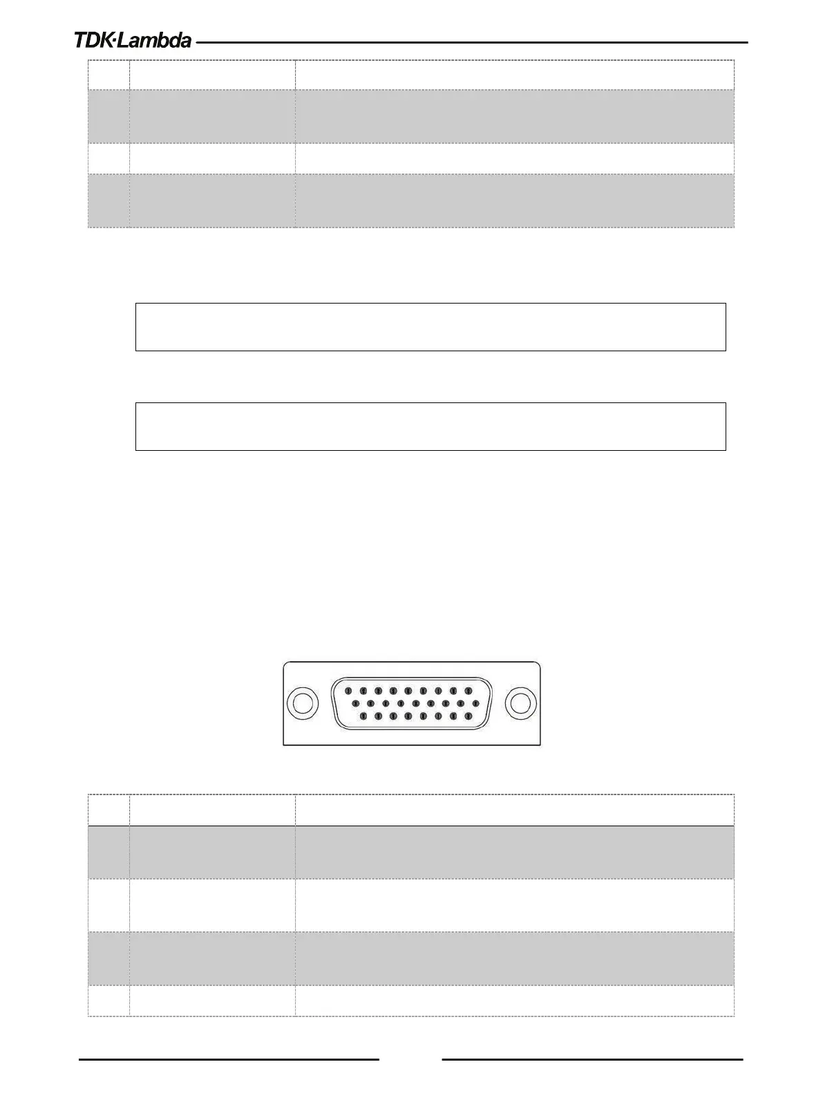
Figure 1–5: J1 Connector Terminals and Functions
1 Daisy In / SO Input for Series Operation / Input for Shut Off control of the power supply
2 Daisy Out / PS_OK #2 Output for Series Operation / Output #2 for indication of power supply
status. High level is OK.
3 PS_OK #1 Output #1 for indication of power supply status. Open Collector type, low
Output for Constant-Voltage / Constant-Current mode indication.