STEPRACE: Service & Maintenance Manual - rev. 1.2
Page 7.10
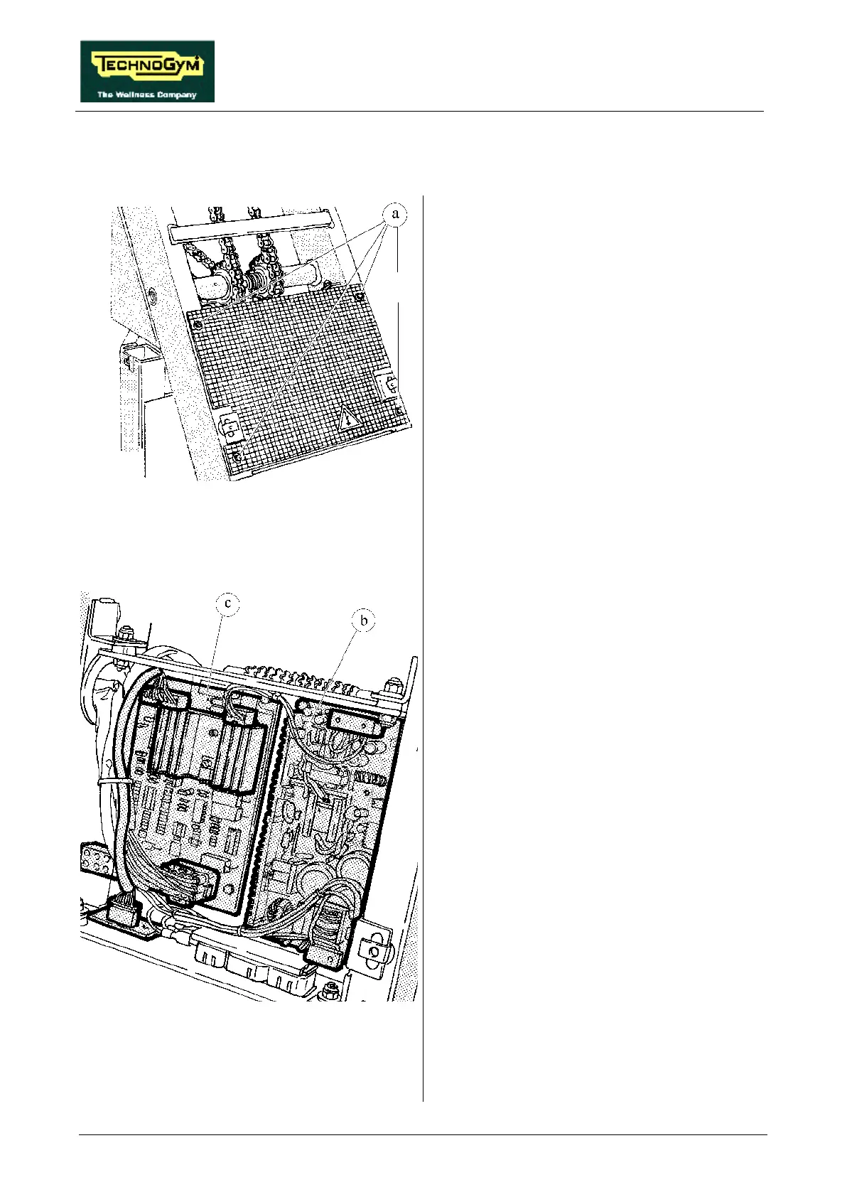
7.7. DISASSEMBLING THE ELECTRONIC CIRCUIT BOARDS
Carry out the procedures described in paragraph
7.6. “Disassembling the upright guard”.
1. Back off the 4 screws a using a medium
Philips screwdriver.
2. Remove the protective grill from the circuit
boards.
Figure 7.7-1
To disassemble the POWER SUPPLY b:
Figure 7.7-2
3. Disconnect the 2 connectors CN1 and CN2.
4. Back off the 4 screws which fix the board to
the plate support, using a 7-mm socket
wrench.
5. Remove the circuit board.
To disassemble the ALTERNATOR
INTERFACE BOARD c:
1. Disconnect the 4 connectors CN1, CN2, CN3
and CN4.
2. Back off the 4 screws which fix the board to
the plate support using a 7-mm socket
wrench.
3. Remove the circuit board.
To disassemble the POWER RESISTOR
positioned on the rear side of the plate support:
1. Back off the 2 nuts securing cable ST-5 using
a 7-mm wrench.
2. Back off the 2 nuts securing the resistor using
a 10-mm wrench.
3. Remove the resistor.
To reassemble the ELECTRONIC CIRCUIT
BOARDS, carry out the above steps in reverse
order.