EasyManua.ls Logo

Tecnoware EVO DSP PLUS MODULAR - Control Panel Description; Introduction

Tecnoware EVO DSP PLUS MODULAR
104 pages
Print Icon
To Next Page IconTo Next Page
To Previous Page IconTo Previous Page
Loading...
ENGLISH
User’s manual 18 UPS EVO DSP PLUS Modular
5 Control Panel Description
5.1 Introduction
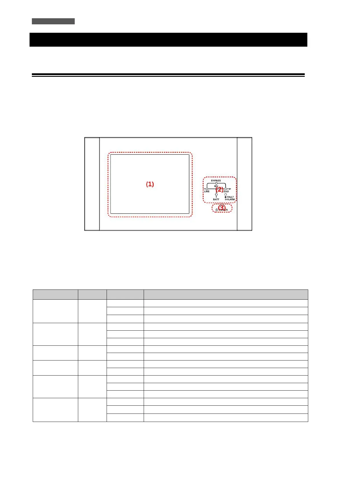
At the top of the front door, there is the Control Panel (see Figure 5.1).
The Control Panel which is divided into 3 parts: (1) 10-inch Touchscreen LCD Display, (2) LED indications, (3)
Control Keys.
All the electrical measurements, parameters, settings, UPS status, battery status and any alarms are displayed on
the LCD Display.
In addition, the UPS emits, during operation, acoustic signals through a buzzer (refer to Table 5-3).
Figure 5.1 Control Panel
(1) 10 inch Touchscreen LCD Display
(2) LED indications (refer to Table 5-1)
(3) Control Key (refer to Table 5-2)
Table 5-1: LED Indications
LED
Color
Status
Definition
LINE
Green
ON
Input source is normal
Flashing
Input source is abnormal
OFF
No Input source
BYPASS
Yellow
ON
Load on Bypass
Flashing
Input source is abnormal
OFF
Bypass not operating
LOAD
Green
ON
There is power output for the load.
OFF
There is no power output for the load.
INV
Green
ON
Load on Inverters
OFF
Inverters not operating
BATTERY
Red
ON
Load on Battery
Flashing
Low Battery
OFF
Battery Converter is normal and Battery is charging
FAULT/ALARM
Red
ON
UPS fault
Flashing
UPS alarm
OFF
Normal

Related product manuals