Specification-2445A/2455A Service
Table
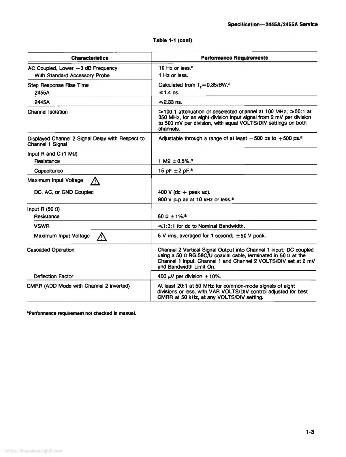
1-1
(cont)
Characteristics
Performance Requirements
AC Coupled, Lower
-3
dB
Frequency
10 Hz
or
less.
8
With Standard Accessory Probe
1 Hz
or
less.
Step Response Rise Time
Calculated from Tr=0.35/BW. (a)
2455A
<= 1.4
ns.
2445A
<= 2.33
ns.
Channel Isolation
>= 100:1
attenuation
of
deselected channel at 100 MHz;
>= 50:1
at
350 MHz, for
an
eight-division input signal from 2 mV per division
to
500
mv
per division, with equal VOL TS/DIV settings on both
channels.
Displayed Channel 2 Signal Delay with Respect to
Adjustable through a range
of
at least
-500
ps
to
+500
ps.
8
Channel 1 Signal
Input R and C
(1
þÿM©)
Resistance
1
þÿM©
±0.5%.
8
Capacitance 15 pF
±2
pF.
8
Maximum Input Voltage
DC,
AC,
or
GND Coupled 400 V (de + peak ac).
800 V p-p ac at 10 kHz
or
less.
8
Input R (50
þÿ©)
Resistance 50 þÿ©
±1%.
8
VSWR
<=1
:3:1 for de to Nominal Bandwidth.
Maximum Input Voltage
5 V rms, averaged for 1 second; ± 50 V
peak.
Cascaded Operation Channel 2 Vertical Signal Output into Channel 1 input;
DC
coupled
using a 50 þÿ© RG-58C/U coaxial cable, terminated in 50
þÿ© at
the
Channel 1 input. Channel 1 and Channel 2 VOL TS/DIV set at 2 mV
and Bandwidth Limit On.
Deflection Factor 400
µV
per division ± 10%.
CMRR (ADD Mode with Channel 2 inverted)
At
least 20: 1
at
50 MHz for common-mode signals
of
eight
divisions
or
less, with VAR VOL TS/DIV control adjusted for best
CMRR at 50 kHz,
at
any VOL TS/DIV setting.
•Performance
requirement
not
checked
In
manual.
1-3