Speclfication-2445A/2455A
Service
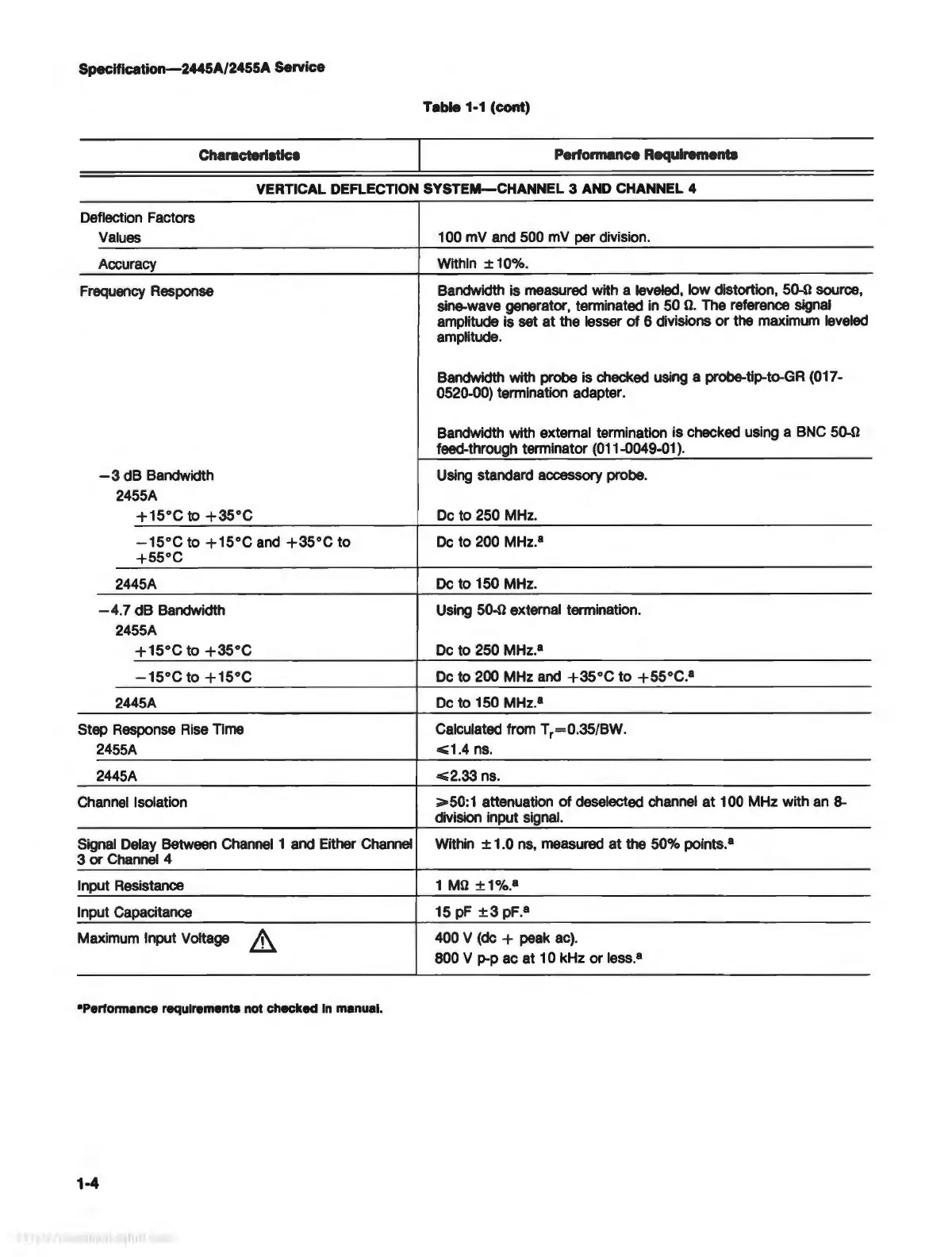
Table 1-1
(cont)
Characterlatlca
Pertonnance Requirements
VERTICAL DEFLECTION
SYSTEM-CHANNEL
3 AND CHANNEL 4
Deflection Factors
Values
100 mV and 500 mV per division.
Accuracy
Within
± 10%.
Frequency Response
Bandwidth is measured with a leveled, low distortion, þÿ50©source,
sine-wave generator, terminated in 50
þÿ©.
The reference signal
amplitude is
set
at
the lesser
of
6 divisions
or
the maximum leveled
amplitude.
Bandwidth with probe is checked using a probe-tip-to-GR (017-
0520-00) termination adapter.
Bandwidth with external termination
is
checked using a BNC þÿ50©
feed-through terminator (011-0049-01
).
-3
dB
Bandwidth
Using standard accessory probe.
2455A
+15°C
to
+35°C
De
to
250 MHz.
-15°C
to
+15°C
and
+35°C
to
De
to
200 MHz.
8
+55°C
2445A
De
to
150 MHz.
-4
.7
dB
Bandwidth
Using þÿ50© external termination.
2455A
+15°C
to
+35°C
De
to
250 MHz.
8
-15°C
to
+15°C
De
to
200 MHz and
+35°C
to
+55°C.
8
2445A
De
to
150 MHz.•
Step Response Rise Time Calculated from
Tr=0.35/BW.
2455A
<=1.4
ns.
2445A
<=2.33
ns.
Channel Isolation
>=50:1
attenuation
of
deselected channel
at
100 MHz with an 8-
division input signal.
Signal Delay Between Channel 1 and Either Channel Within
± 1.0 ns, measured
at
the 50% points.
8
3
or
Channel 4
Input Resistance
1
þÿM©
±1%
.
8
Input Capacitance
15 pF
±3
pF.
8
Maximum Input Voltage 400 V
(de+
peak ac).
800 V p-p ac at 1 0 kHz
or
less.
8
•Perfonnance
requirements
not
checked
In
manual.
1-4