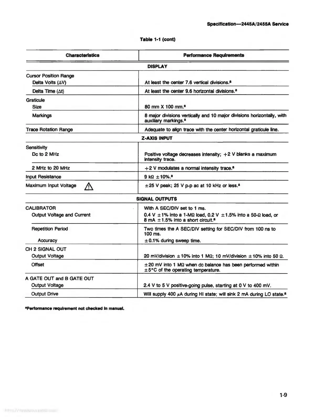
Characterlatlcs
Cursor Position Range
Delta Volts þÿ(”
V)
Delta Time þÿ(”t)
Graticule
Size
Markings
Trace Rotation Range
Sensitivity
De
to 2 MHz
2 MHz to 20 MHz
Input Resistance
Maximum Input Voltage
CALIBRATOR
Output Voltage and Current
Repetition Period
Accuracy
CH
2 SIGNAL OUT
Output Voltage
Offset
A GATE OUT and 8 GATE OUT
Output Voltage
Output Drive
•Performance
requirement
not
checked
In
manual.
Specltlcation-2445A/2455A
Service
Table
1-1
(cont)
Performance
Requirements
DISPLAY
At
least the center 7.6 vertical divisions.•
At
least the center 9.6 horizontal divisions.•
80
mm
X 100 mm.•
8 major divisions vertically and 10 major divisions horizontally, with
auxiliary markings.•
Adequate
to
align trace with the center horizontal graticule line.
Z-AXIS INPUT
Positive voltage decreases intensity;
+2
V blanks a maximum
intensity trace.
+ 2 V modulates a normal intensity trace.•
9
þÿk©
±10%.
8
±25
V peak;
25
v
P-P
ac at 10 kHz or less.•
SIGNAL OUTPUTS
With A SEC/DIV set to 1 ms.
0.4 V ± 1 % into a
þÿ1M©
load, 0.2 V ± 1.5% into a þÿ50©load, or
8 mA ± 1.5% into a short circuit.
8
Two times the A SEC/DIV setting for SEC/DIV from 100 ns
to
100 ms.
±
0.1
% during sweep time.
20 mV/division
±10%
into 1
þÿM©;
10 mV/dlvision
±10%
into 50
þÿ©.
± 20 mV into 1
þÿM©
when
de
balance has been performed within
±5°C
of
the operating temperature.
2.4 V to 5 V positive-going pulse, starting
at
0 V
to
400 mV.
Will supply 400 µA during
HI
state; will sink 2 mA during LO state.•
1-9