Theory
of
Operation-2445A/2455A Service
U300
are
reduced
by
the tracking regulator circuit com-
posed
of
U165A, 0190,
and
associated components.
Operational amplifier U165A
and
0190
is
configured so
that the output of voltage at the emitter
of
0190 follows
the
-5-V
supply applied to R198. This tracking arrange-
ment ensures that the supply voltages
are
of
equal magni-
tudes to minimize de offsets
in
the output signals.
Scale
Illumination
The
Scale Illumination circuit consists of U130C,
U130D,
U130E, U130F,
and
associated components. The
circuit enables the operator to adjust the illumination
level
of
the
graticule marks
on
the crt face plate using the
SCALE ILLUM control.
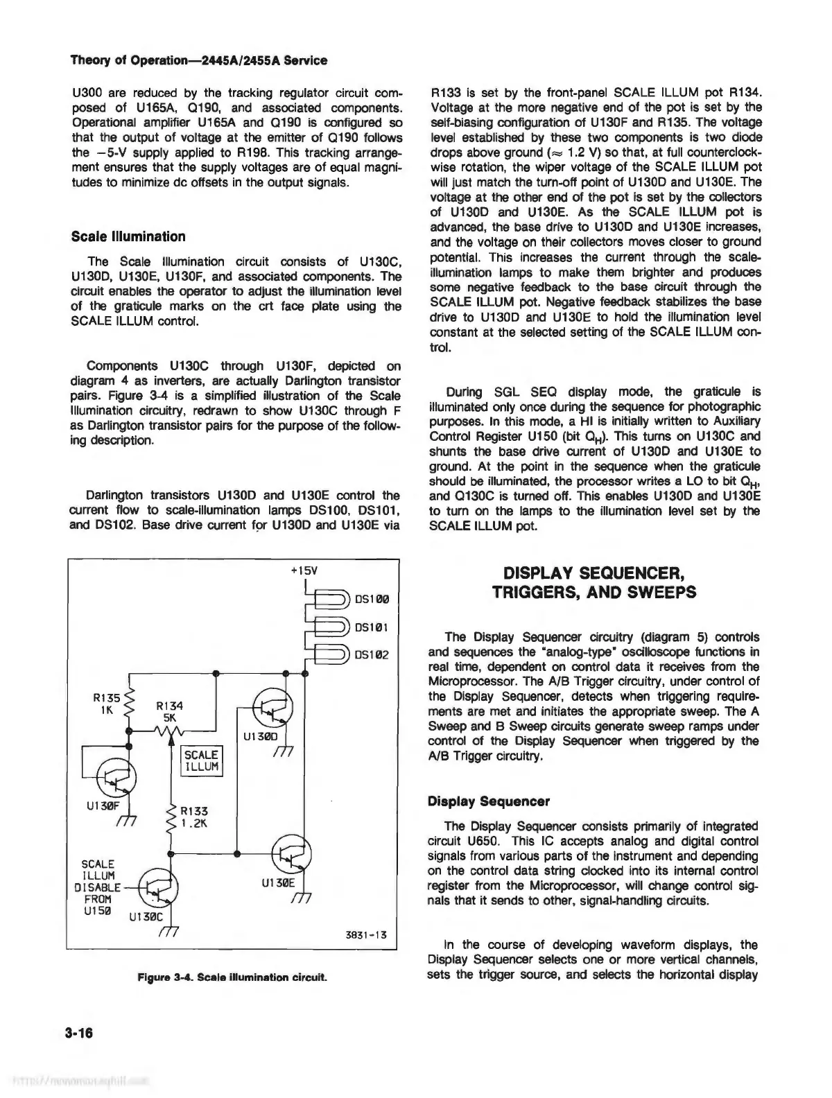
Components U130C through U130F, depicted
on
diagram 4
as
inverters,
are
actually Darlington transistor
pairs. Figure 3-4
is
a simplified illustration of the Scale
Illumination circuitry, redrawn to show U130C through F
as
Darlington transistor pairs for the purpose of the follow-
ing
description.
Darlington transistors U130D
and
U130E control the
current flow to scale-illumination lamps DS100, DS101,
and
DS102. Base drive current for U130D
and
U130E via
+15V
3831-13
Figure 3-4. Scale illumination circuit.
3-16
R133
is
set
by
the front-panel SCALE ILLUM pot R134.
Voltage at the more negative
end
of the pot is set
by
the
self-biasing configuration of U130F
and
R135.
The
voltage
level
established
by
these two components
is
two diode
drops above
ground(=
1.2
V)
so that,
at
full counterclock-
wise rotation, the wiper voltage of the SCALE ILLUM pot
will just match the turn-off point of U130D
and
U130E. The
voltage at the other
end
of the pot
is
set
by
the collectors
of U130D
and
U130E. As the SCALE ILLUM pot is
advanced, the
base
drive to U130D
and
U130E increases,
and
the voltage
on
their collectors moves closer to ground
potential. This increases the current through the scale-
illumination lamps to make them brighter
and
produces
some negative feedback to the base circuit through the
SCALE ILLUM pot. Negative feedback stabilizes the base
drive to U130D
and
U130E to hold the illumination
level
constant at the selected setting of the SCALE ILLUM con-
trol.
During SGL
SEQ
display mode, the graticule
is
illuminated only once during the sequence for photographic
purposes.
In
this
mode,
a
HI
is
initially written to Auxiliary
Control Register U150 (bit
QH)
. This turns
on
U130C
and
shunts the base drive current
of
U130D
and
U130E to
ground.
At
the point
in
the sequence
when
the graticule
should
be
illuminated, the processor writes a
LO
to bit
QH
,
and
Q130C
is
turned off. This enables U130D
and
U130E
to turn
on
the lamps to the illumination level set
by
the
SCALE ILLUM pot.
DISPLAY SEQUENCER,
TRIGGERS, AND SWEEPS
The Display Sequencer circuitry (diagram
5)
controls
and
sequences the ·analog-type" oscilloscope functions
in
real
time, dependent
on
control data it receives from the
Microprocessor.
The
A/B Trigger circuitry, under control
of
the Display Sequencer, detects when triggering require-
ments
are
met
and
initiates the appropriate sweep. The A
Sweep
and
B Sweep circuits generate sweep ramps under
control of the Display Sequencer
when
triggered
by
the
A/B Trigger circuitry.
Display Sequencer
The
Display Sequencer consists primarily of integrated
circuit U650. This
IC
accepts analog
and
digital control
signals from various parts
of
the instrument
and
depending
on
the control data string clocked into its internal control
register from the Microprocessor, will change control sig-
nals that it sends to other, signal-handling circuits.
In
the course of developing waveform displays, the
Display Sequencer selects one or more vertical channels,
sets the trigger source, and selects the horizontal display