Getting started
AFG31000 Series Arbitrary Function Generator User's Manual 31
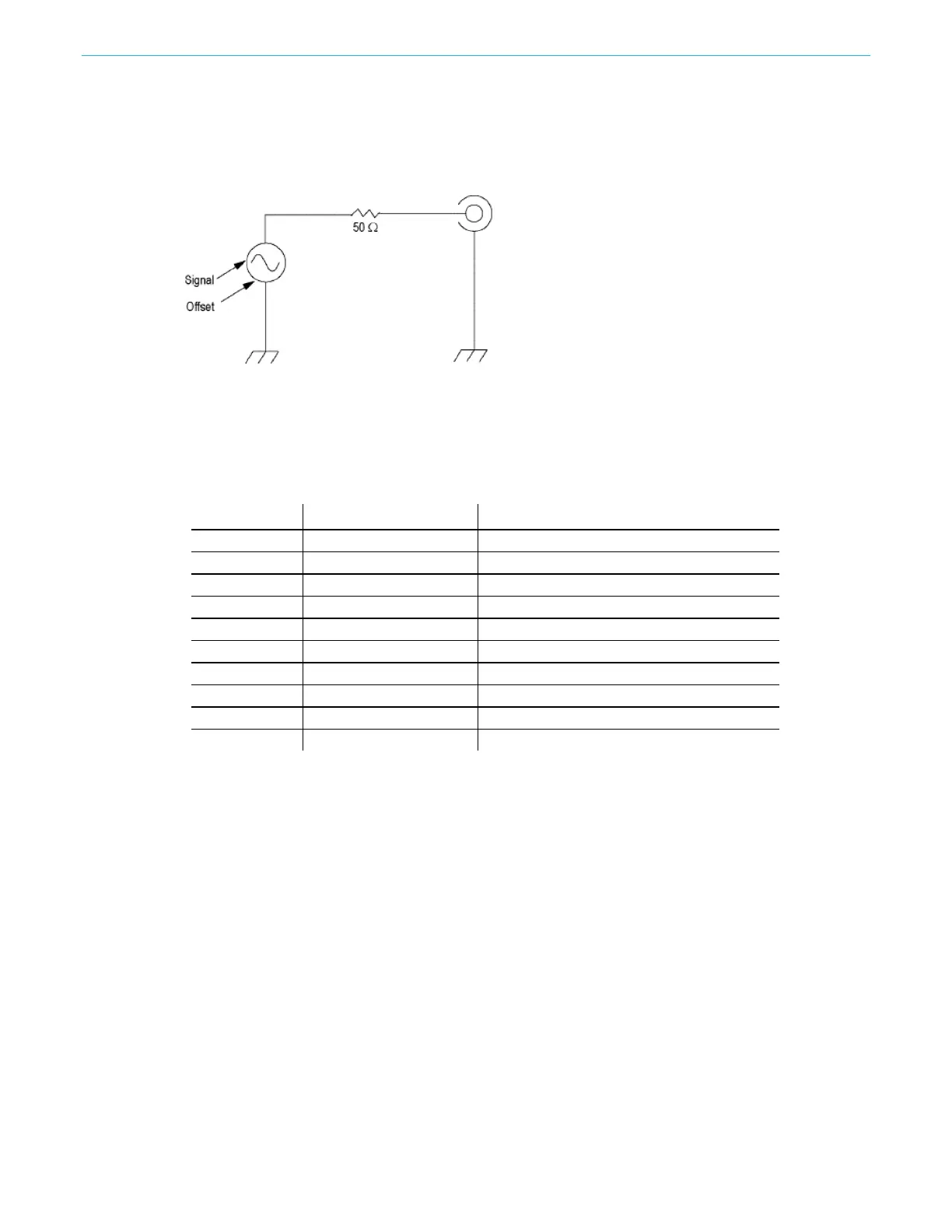
Equivalent output circuits
The following figure shows the equivalent output circuits for the AFG31000 Series Arbitrary Function
Generator instruments:
Figure 5: AFG output circuits
The following table shows the output window (minimum and maximum levels) for a sine waveform
when you change the load impedance (L). Load impedance affects the output window.
Table 5: Output window for a sine waveform
Instruments Minimum amplitude Maximum amplitude
31021
pp
pp
pp
pp
31052
5 V to –5 V (10 V
pp
) 10 V to –10 V (20 V
pp
)
31101
pp
pp
pp
pp
31152
2.5 to –2.5 (5 V
pp
) 5 V to –5 V (10 V
pp
)
31251
pp
pp
pp
pp
Protection from overheating
The internal temperature of the AFG31000 Series instrument is monitored. A warning message is
displayed if the internal temperature reaches a specified level and signal output is automatically
turned off.
If the warning message appears, check for the following conditions:
The ambient temperature requirement is correct.
The required cooling clearance has been provided.
The instrument fan is working properly.
 Loading...


