Get Acquainted w
ith the Instrument
18. The bus display
shows decoded packet
level information for serial buses or for
parallel buses (MSO4000B Series only).
The bus indica
tor shows the bus number
and bus type.
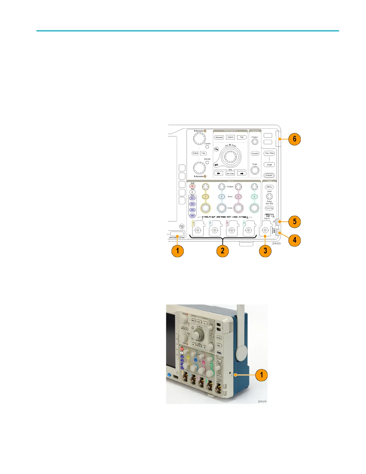
Front Panel Connectors
1. Logic Probe Connector (on
MSO4000B models only)
2. Channel 1, 2, 3, 4. Channel inputs with
TekVPI Versatile Probe Interface.
3. Aux In. Trigger level range is adjustable
from +8 V to -8 V. The maximum input
voltage is 400 V
pe
ak
, 250 V
RMS
. Input
resistance is 1 MΩ ± 1% in parallel w ith
13 pF ±2 pF.
4. PROBE COMP. Square wave signal
source to compensate or calibrate
probes. Output voltage: 0 – 2.5 V,
amplitude ± 1% behind 1 kΩ ±2%.
Frequency: 1 kHz.
5. Ground.
6. Application Module Slots.
Side-Panel Connector
1. Ground strap connector. This is a
receptacle for a grounding strap.
MSO4000B and DP O4000B Series Oscilloscopes User Manual 43

 Loading...


