Get Acquainted w
ith the Instrument
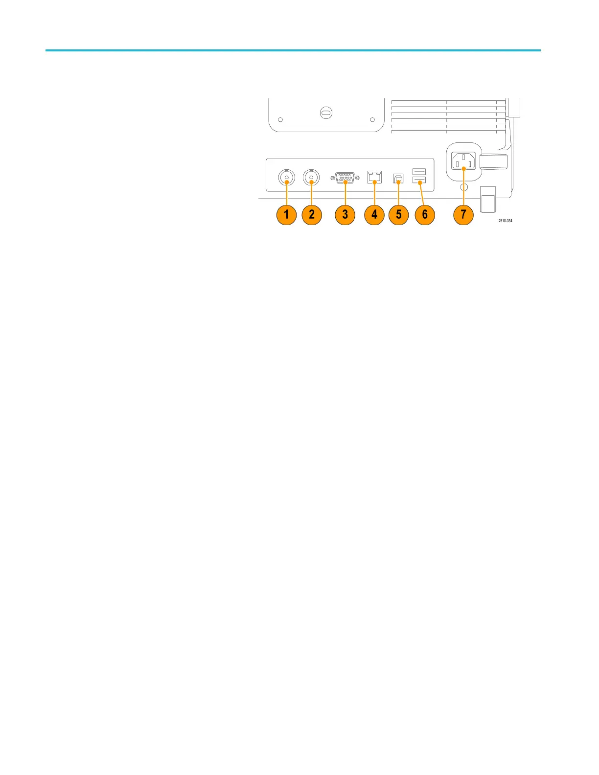
Rear-Panel Connectors
1. Auxiliary Out
put. Use this output to
generate a signal on a main trigger
pulse, as a 10 MHz reference signal,
or to output a s
ignal when other events
happen, such as mask-limit test events.
To use this to synchronize other test
equipment wi
th your oscilloscope, push
Utility on the front panel, then Utility
Page on the bottom menu, and select
External Si
gnals with multipurpose
knob a. Push AUX OUT on the bottom
menu and Main Trigger on the resulting
side menu.
AHIGHtoLO
W transition indicates that
the trigger occurred. The logic l evel for
Vout (HI) is ≥2.5 V open circuit; ≥1.0 V
intoa50Ω
load to ground. The logic
level for Vout (LO) is ≤0.7 V into a load
of ≤4mA;≤0.25 V into a 50Ω load to
ground.
2. EXT R EF IN. You can connect an
externa
l clock to this connector. To
enable this connector, push Utility on
the front panel, then Utility Page on
the bot
tom m enu, and select External
Signals with multipurpose knob a. Push
Reference Source on the bottom menu
and EXT
REF IN from the resulting side
menu.
3. XGA Out. Use the XG A Video port
(DB-15 female connector) to show the
osci
lloscope display on an external
monitor or projector.
4. LAN. Use the LAN (Ethernet) port (RJ-45
connector) to connect the oscilloscope to
a10
/100 Base-T local area network.
MSO4000B and DPO4000B models are
LXI Class C version 1.3 compliant.
44 MSO4000B and DPO 4000B Series Oscilloscopes User Manual

 Loading...


