MX32v2
ANALOG AND DIGITAL CONTROLLER
USER MANUAL
Revision D.0
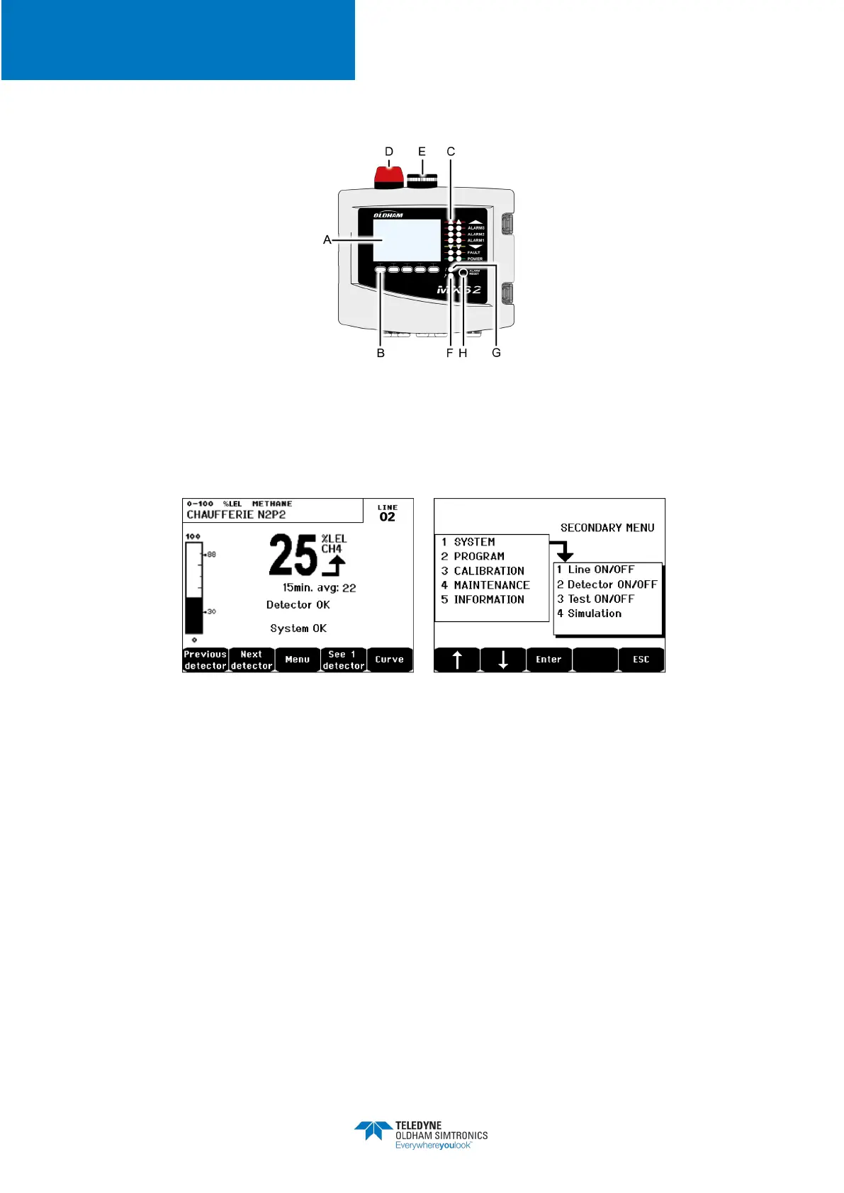
4.2 Front Plate
Figure 9:
MX32v2
’s front plate
4.2.1 LCD (A)
The display shows the measurements or the settings menus. When an alarm occurs, the display
turns in grayscale mode to indicate the channel that is currently displayed is on alarm.
Figure 10: Display of the measurement (on the left) or parameter settings display (on the right)
Refer to paragraph
Menus
on page 41 for more details about the information that are available
on the screen.
4.2.2 Contextual Keys (B)
The function of each of the 5 keys indicated in the lower part of the display changes depending
on the page displayed.Zone Status Indicators (C)
The two bars of 7 indicators represent two zones. The detectors that are connected to the
controller can be assigned to one of the two zones by using
COM 32
configuration software.
Each bar displays the status of the group of detectors of the pertinent zone as follows: