Do you have a question about the TELEDYNE OLDHAM SIMTRONICS MX32 and is the answer not in the manual?
Instructions must be read thoroughly before installation and start-up for end-user safety.
Explains icons for useful information and earth/protective ground connections.
Details safety labels, qualified personnel for installation, and cable temperature requirements.
Covers warranty cancellation due to modifications and adherence to specified technical characteristics.
Teledyne Oldham Simtronics disclaims liability for damages and losses related to product use.
Outlines a two-year warranty on parts and workmanship, excluding consumables.
Controller for continuous measurement and control of gases in the atmosphere.
Details the 1 line, 2 lines, and Bridge versions of the MX32v2 controller.
Explains the information provided on the unit's firmplate, including model and certifications.
Software used for setting MX32v2 parameters from a PC.
Details location requirements and wall enclosure attachment for the MX32v2 controller.
Provides instructions on location and fixing of gas detectors for optimal performance and safety.
Describes the location and DIN rail mounting of digital modules in electrical cabinets.
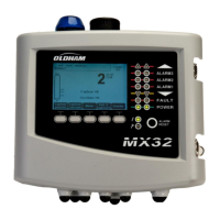
Details the external view of the MX32v2, identifying its components and indicators.
Describes the LCD display, contextual keys, and zone status indicators on the front panel.
Explains alarm thresholds, internal relays, buzzer, and automatic/manual acknowledgement settings.
Details the information found on the firmplate, including model, specs, and markings.
Lists available addressable digital modules for the MX32v2 system.
Details RS485 network topology, cabling, and communication setup for digital modules.
Describes the function, introduction, connection, and configuration of relay modules.
Details the function, introduction, connection, and configuration of the 16-logic input module.
Covers the function, introduction, connection, and configuration of the 8-analog input module.
Explains the function, introduction, connection, and configuration of the 4-analog output module.
Details power supply, grounding, digital/analog lines, and relay connections for the controller.
Provides wiring diagrams for 4/8-Relay, 16-Logic Input, 8-Analog Input, and 4-Analog Output modules.
Provides a visual tree of the MX32v2's main menu categories and their sub-menus.
Explains the function of each navigation key (up, down, enter, escape) for menu interaction.
Describes the measurement display in normal mode, including indicators and trends.
Covers System Info, Passwords, Date/Time, Display Settings, and Language options.
Details options for Buzzer, Tag Set, Alarm Settings, and RS485 Port configuration.
Guides through detector selection, recording, validation, sensor exchange, and operating modes.
Covers line/detector on/off, test mode, and simulation features for system upkeep.
Explains how to view detector info, alarm/fault records, I/O status, and operating events.
Lists main part numbers, references, and images for various MX32v2 modules and kits.
Details part numbers for accessories like RS485 boards, power supplies, fuses, and batteries.
Provides instructions on cleaning the controller exterior with a damp cloth, avoiding specific liquids.
Details the safe procedure for replacing fuses, requiring qualified personnel and power off.
Outlines the procedure for replacing the lithium battery, emphasizing safety and qualified personnel.
Presents the EU Declaration of Conformity, listing directives and applied standards for the MX32v2.
Details functions, lines, display, indicators, keys, alarms, limits, and internal relays for the controller.
Provides electrical, mechanical, environmental, and standard specifications for the MX32v2 system.
Details specifications for the Relay Module, including function, number of relays, and terminals.
Outlines specifications for the 16-Logic Input Module, including capacity, terminals, and consumption.
Lists specifications for the 8-Analog Input Module, including function, capacity, and consumption.
Details specifications for the 4-Analog Output Module, covering capacity, logic inputs, and consumption.
Details the RS485 communication card, its LEDs, connection terminals, and EOL resistance.
Explains accessing configuration and real-time sensor data via the RS485 transfer table.
Covers supervision, configuration, and data acquisition for MX32v2 sensors via Modbus.
Presents reliability data (MTBF, SFF, PFDavg) and SIL 1 certification for the MX32v2 controller.
Details how the controller processes detector signals and activates alarms for safety.
Provides ATEX compliance information and specific instructions for preventing explosions.
Shows the controller status based on detector analog signal output (mA) and fault conditions.
| Brand | TELEDYNE OLDHAM SIMTRONICS |
|---|---|
| Model | MX32 |
| Category | Controller |
| Language | English |