MX32v2
ANALOG AND DIGITAL CONTROLLER
USER MANUAL
Revision D.0
5.3.1 End Of Line Resistor
For the last module only of each line, set switch #8 (EOL
RESISTOR/RESISTANCE F.D.L.) to ON or set the jumper of the
Analog Input Module to
Closed
(Figure 19
ModuleN).
Figure 13: End Of Line
Resistor is set to ON
5.4 Relay modules
5.4.1 Function
.
T
his digital module, available in two versions,
allows for the management of:
outputs;
• or 1 to 8 relays.
In addition, it has 2 logic inputs.
Figure 14: 8 relay module
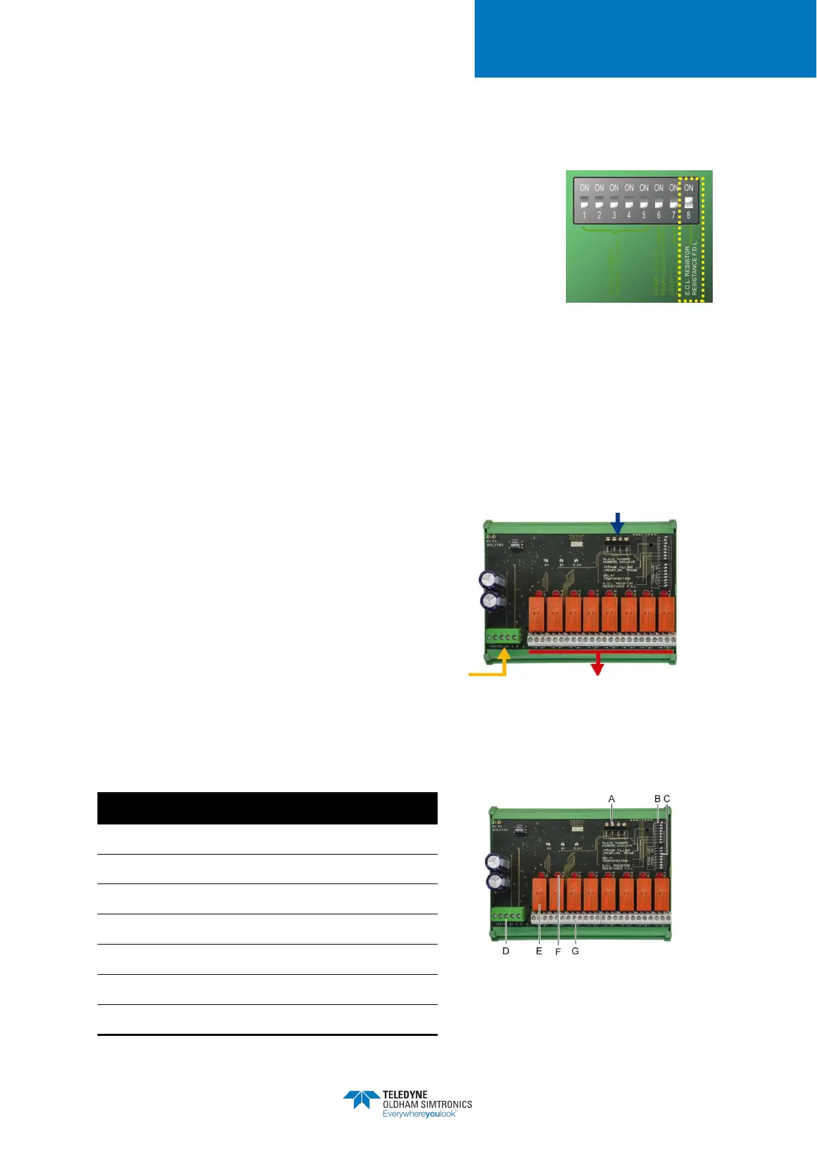
5.4.2 Introduction
Figure 15: 8 relay module
A.
Logic Inputs
B.
DIP switches for module configuration
C.
DIP switches for relays configuration
Power supply and RS485 network
Programmable relays (4 or 8)
F.
Relay status visual indicators
G.
Relay terminals
2 logic inputs
4 wire serial cable