MX32v2
ANALOG AND DIGITAL CONTROLLER
USER MANUAL
Revision D.0
. Reactivation time: If checked, time is adjustable between 15 and 900 seconds, beyond
which the relay is reactivated.
Controls of the alarm relay
• Logic equations of up to 4 levels of parentheses by the logic operators OR, AND, NOR,
and NAND. The result of the equation drives the relay
• Vote (x over y). There must be at least “x” events over the total of “y” to activate the
relay. Optionally, the user may define whether a failure is considered as an alarm.
F – Relay status indicator
The status of each relay is visualized by a red LED:
• LED is OFF: the coil is not powered
• LED is ON: the coil is powered
G – Relay output connectors
Overvoltage Category II. Contact rating is 2A @ 250Vac or 30Vdc.
5.4.3 Connection
Refer to chapter 6, on page 33
5.4.4 Configuration
Configured via the
COM 32
application
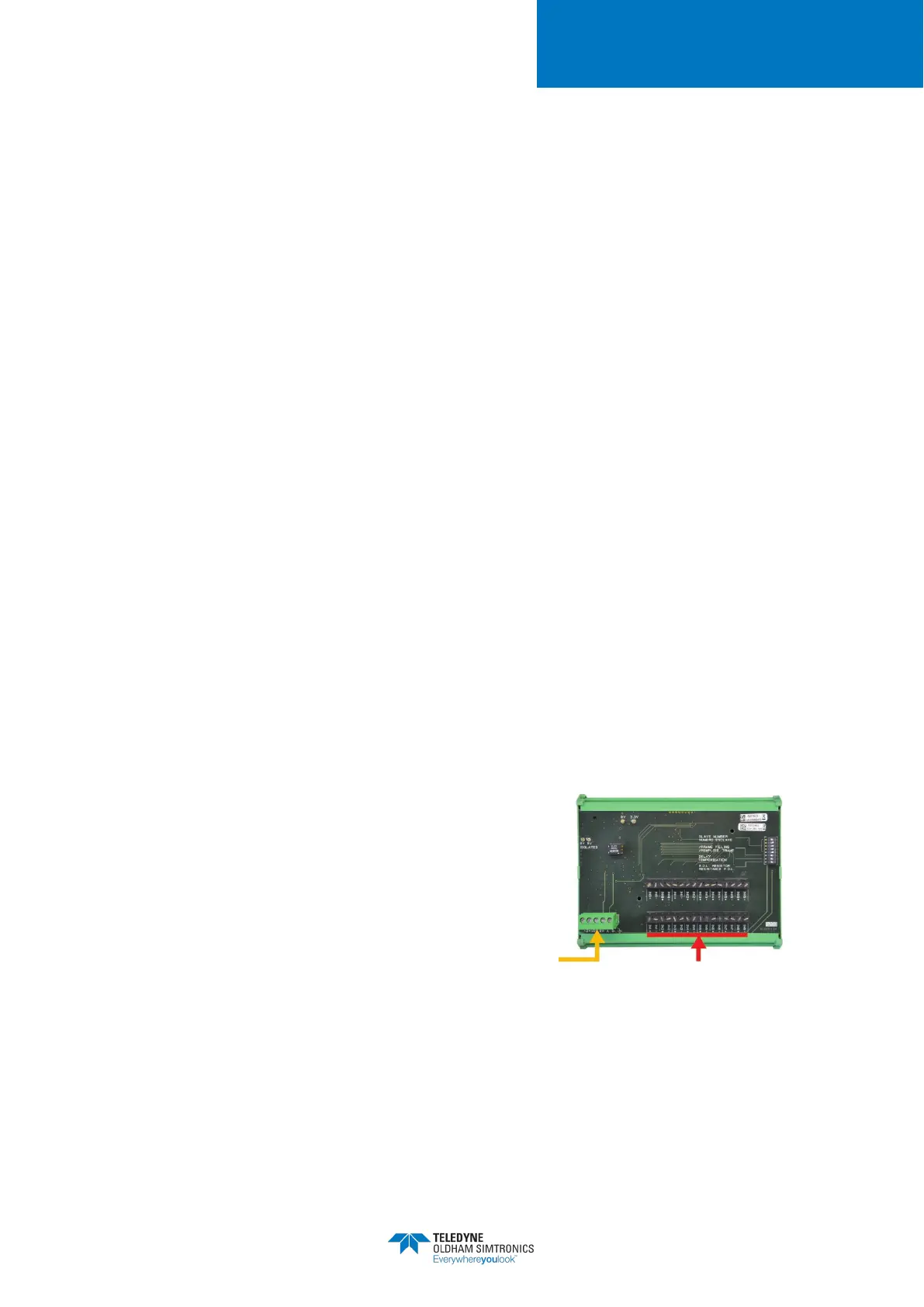
5.5 16-Logic Input ModuleFunction
This digital module allows the monitoring of 1 to 16
dry logic inputs. The controller can manage up to 16
logicnputs limited to 2 modules.
Figure 16: 16 Logic Input Module
16 logic inputs 4 wire serial cable