MX32v2
ANALOG AND DIGITAL CONTROLLER
USER MANUAL
Revision D.0
5.5.2 Introduction
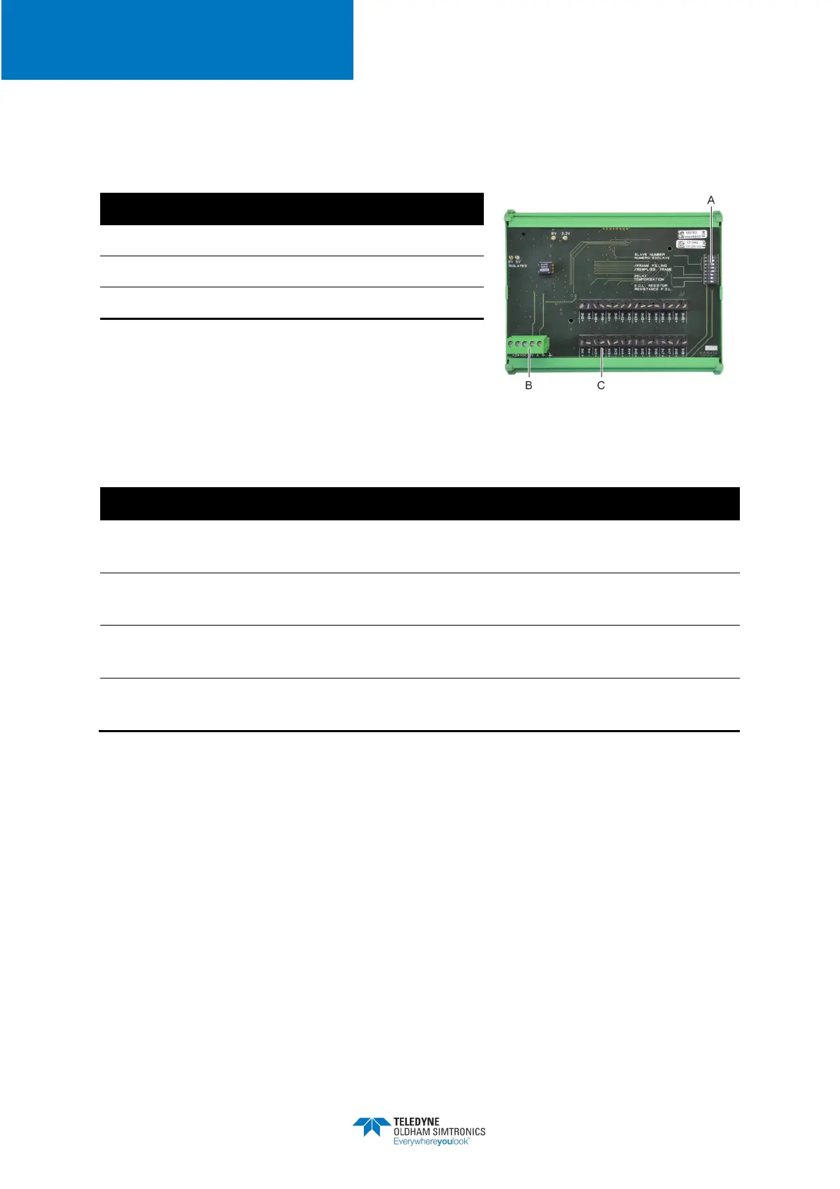
Figure 17: 16 Logic Input Module
A.
DIP switches for module configuration
B.
Power supply and RS485 network
C.
Logic inputs 1 to 16
A – DIP switchesThese DIP switches are set according to the following table:
Slave number
Numéro esclave
See details in the paragraph
Module Address
on page 22
Frame filling
Remplissage de trame
Factory settings. Do not modify
Temporisation
Factory settings. Do not modify
E.O.L Resistor
Résistance F.D.L.
See details in paragraph
End of line Resistor,
on page 24
Table 7: Configuration DIP switches of the
Logic Input Module
C – Logic input connectorsEach of these 16 inputs can be connected to a voltage-free contact
as per Figure 30. Input status is transmitted by the digital line to the
MX32v2
. There is no alarm
when the contact is closed.
5.5.3 Connection
Refer to Chapter 6, on page 33
5.5.4 Configuration
Configured via the
COM 32
application