ST Series Power Supply Instruction Manual INSTALLATION
telemark.com 32 of 64 Rev 1.0.0
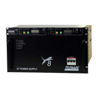
3.4.2 Filament Output Transformer Connections
Figure 3-7, Filament Output Transformer Connections to HVPS
A – J4 HV INPUT >>> connects to J4 of HVPS
B – J7 FILAMENT INPUT >>> connects to J7 of HVPS
C – CHAMBER GROUND >>> (see chapter 3.3 for details)
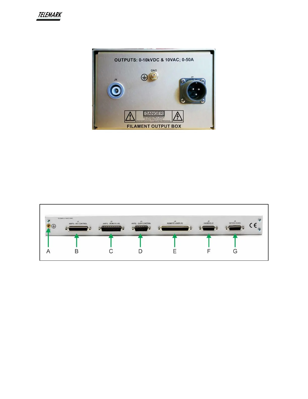
3.4.3 ST Controller Connections
Figure 3-8, ST Controller Rear Panel Connections
A – CHASSIS GROUND >>> (see chapter 3.3 for details)
B – J1 – HVPS HV CONTROL >>> connects to J1 of HVPS
C – J2 – HVPS INTERFACE I/O >>> connects to J2 of HVPS
D – J3 – HVPS - SOURCE CONTROL >>> connects to J3 of HVPS
E – J4 – REMOTE USER I/O >>> connects to Customer I/O (see chapter
5.1)
F – J5 – HANDHELD >>> connects to Handheld
G – J6 – INTERLOCKS >>> connects to Customer I/O (see chapter
3.5)