ST Series Power Supply Instruction Manual STANDARD OPERATION
telemark.com 39 of 64 Rev 1.0.0
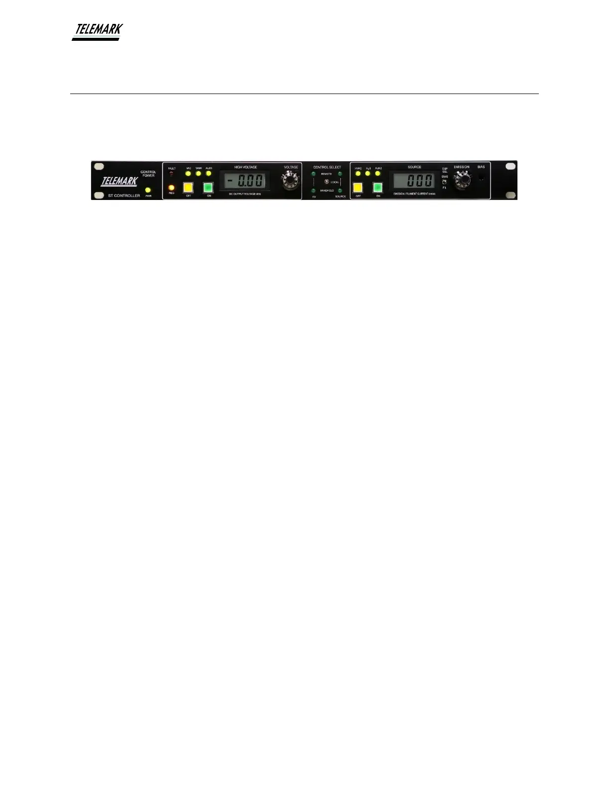
4.2 ST CONTROLLER FUNCTIONS AND INDICATORS
The ST Controller front panel includes a power on indicator and is divided into 3
functional areas:
Local High Voltage Control, Control Input Selection, and Local Source Control
Figure 4-3, Controller Front Panel
1. Controller Power - Green LED that is lit when the HVPS is turned on and input
power is applied.
2. Local High Voltage Control - This area provides local controls and displays the
High Voltage Output on an LCD Display.
3. Control Input Selection – This area lets the user choose which method of input
control to use. (Local, Handheld, or Remote Input via PLC or Process controller)
4. Local Source Control – This area provides local controls and displays the Source
Emission and Source Filament Outputs on an LCD Display.