EasyManua.ls Logo

Telemark ST Series - ST Controller Interlock I;O; Figure 3-11, Interlock Pinouts

Telemark ST Series
64 pages
Print Icon
To Next Page IconTo Next Page
To Previous Page IconTo Previous Page
Loading...
ST Series Power Supply Instruction Manual INSTALLATION
telemark.com 36 of 64 Rev 1.0.0
3.5.2 ST Controller Interlock I/O
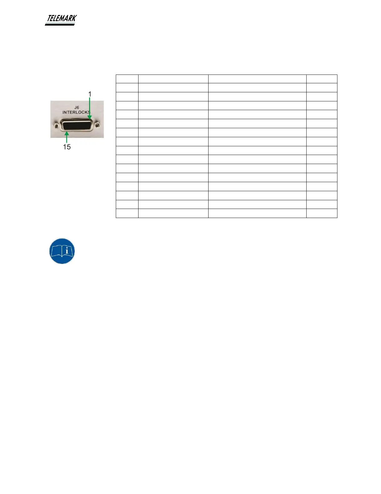
J6 INTERLOCKS External Safety Interlocks (15pin Sub-D M)
Figure 3-11, Interlock Pinouts
NOTE: In the case that interlock inputs need to be paralleled (e.g.
only one safety switch is available for two interlock inputs), it must be
made sure that the Contact closure pins (+15VDC) are wired together and
the Return pins (GND) are wired together (or only one Return pin used).
Failure to do so will compromise correct functioning of the interlocks
(always satisfied).
Example: One safety switch to be used for VAC and HVAC interlocks:
Connect one side of contact to pins 2 and 8 and the other side to pins 1
and 7 (or to only one of the two).
Pin #
Name
Function Description
Power
1
VAC Interlock Return
Return for pin 2
GND
2
VAC Interlock
Contact closure to pin 1
+15VDC
3
TANK Interlock Return
Return for pin 4
GND
4
TANK Interlock
Contact closure to pin 3
+15VDC
5
AUX1 Interlock Return
Return for pin 6
GND
6
AUX1 Interlock
Contact closure to pin 5
+15VDC
7
HVAC Interlock Return
Return for pin 8
GND
8
HVAC Interlock
Contact closure to pin 7
+15VDC
9
H20 Interlock Return
Return for pin 10
GND
10
H20 Interlock
Contact closure to pin 9
+15VDC
11
AUX2 Interlock Return
Return for pin 12
GND
12
AUX2 Interlock
Contact closure to pin 11
+15VDC
13
-
-
-
14
-
-
-
15
-
-
-

Table of Contents

Related product manuals