ST Series Power Supply Instruction Manual REMOTE OPERATION
telemark.com 50 of 64 Rev 1.0.0
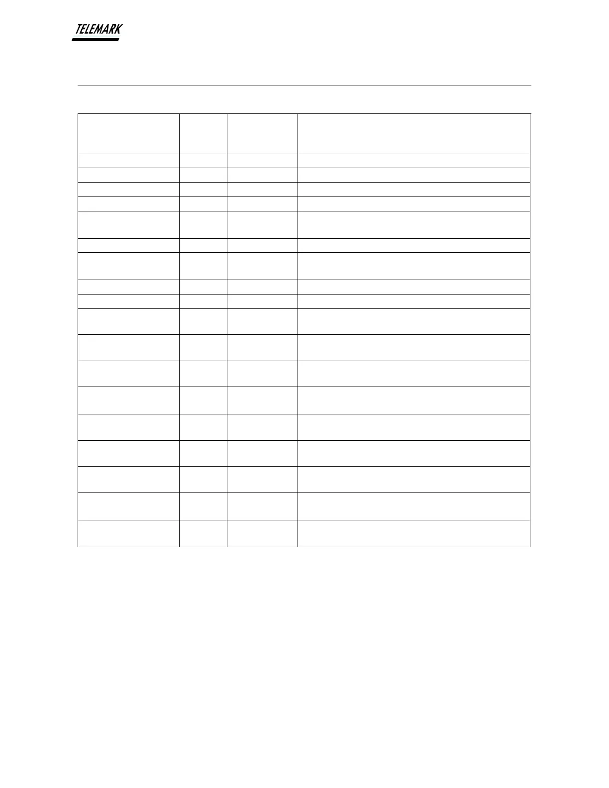
All Interlocks OK
Indicator
Low = All Interlocks satisfied
High = Not all Interlocks satisfied
Source Ready/OFF
Indicator
Low = Source is ready/off
High = Source is not off
Source (if used) for remote Emission reference input
(2mA maximum output)
Source (if used) for remote kV reference input (2mA
maximum output)
External user isolated control power (for output
clamping)
0 to +10VDC = 0 to -10kV
0 to +8VDC = 0 to -8kV (ST-4)
0 to +5 / 6 / 8 / 10VDC = 0 to 500 / 600 / 800mA /
1000mA
Reference for pins 2 thru 6, 9, 10, 24, 31 (isolated from
GND)
Reference for pins 1, 7, 12, 14, 15, 30, 32, 33, 34
Reference for pins 1, 7, 12, 14, 15, 30, 32, 33, 34
Figure 5-2, Remote I/O Pinout, Bottom Row
* O.C. : Denotes Open Collector
Note 1: Open Collector outputs require external pull-up resistors. When connecting
“User +24VDC” to pull-up resistors, their resistance value must not be lower than
2kOhm.
Note 2: When using “User +24VDC” as control supply voltage for pins 2-6, 9, 10, 24
and 26, then GND and GND_ISO must be shorted externally (for example pins 17
and 36).