ST Series Power Supply Instruction Manual REMOTE OPERATION
telemark.com 49 of 64 Rev 1.0.0
Top Row Pins
Source for user +24VDC control (200mA max
output)
Low = HV ready/off
High = HV not ready
Out-of-Regulation
Indicator
Low = HV out of regulation
High = HV regulating
Low = HVPS Fault
High = no HVPS Fault
Low = HV is on
High = HV is off
Low = Source is on
High = Source is off
Jumper only, do
not apply
voltage
Open = always front panel pot
GND = kV reference selected by Control Select
switch
Reference for pins 1, 7, 12, 14, 15, 30, 32, 33, 34
+5 to +24VDC = HV ON
0VDC = HV OFF
+5 to +24VDC = Source ON 0VDC = Source OFF
Jumper only, do
not apply
voltage
Open = ON signals from PLC
GND = F.P. ON switches are active in remote mode
Reference for pins 1, 7, 12, 14, 15, 30, 32, 33, 34
0 to +10VDC = 0 to 10kV
0 to +8VDC = 0 to 8kV (ST-4)
Remote Emission
Current Reference
0 to +10VDC = 0 to max. current
(500 / 600 / 800 / 1000mA)
Reference for pins 2 thru 6, 9, 10, 24, 31 (isolated
from GND)
Reference for pins 2 thru 6, 9, 10, 24, 31 (isolated
from GND)
Reference for pins 1, 7, 12, 14, 15, 30, 32, 33, 34
Reference for pins 1, 7, 12, 14, 15, 30, 32, 33, 34
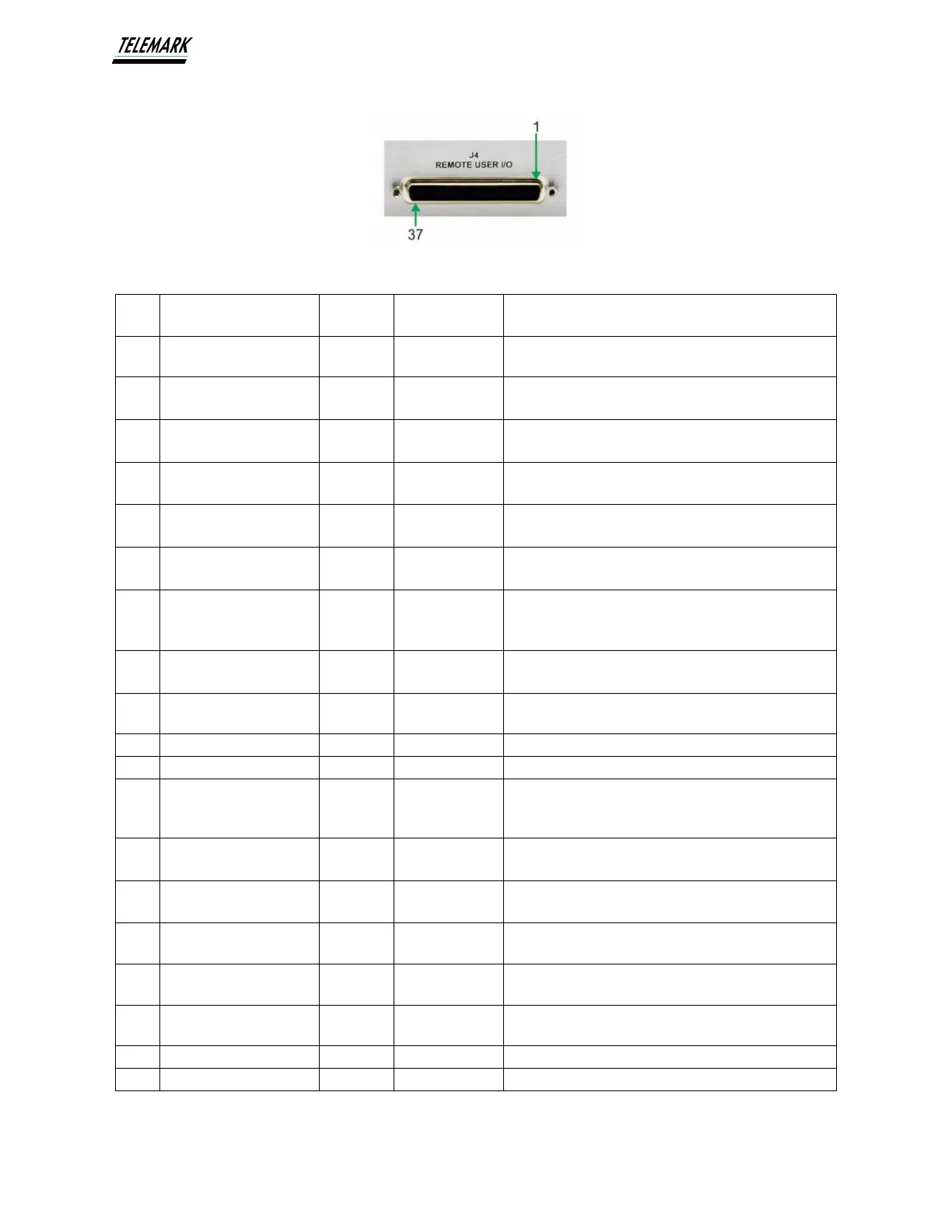
Figure 5-1, Remote I/O Pinout, Top Row