ST Series Power Supply Instruction Manual INSTALLATION
telemark.com 35 of 64 Rev 1.0.0
Figure 3-9, MAIN POWER, Line Input
1. Connect the power connector to the mains cable.
2. Connect the cable connector to the power supply.
3. Connect the cable to the mains outlet.
3.5 INTERLOCK I/O
It is extremely important for operator and equipment safety that the external interlocks
are appropriately installed (see also Chapter 9, connection diagrams Figures 9-1 and 9-
2).
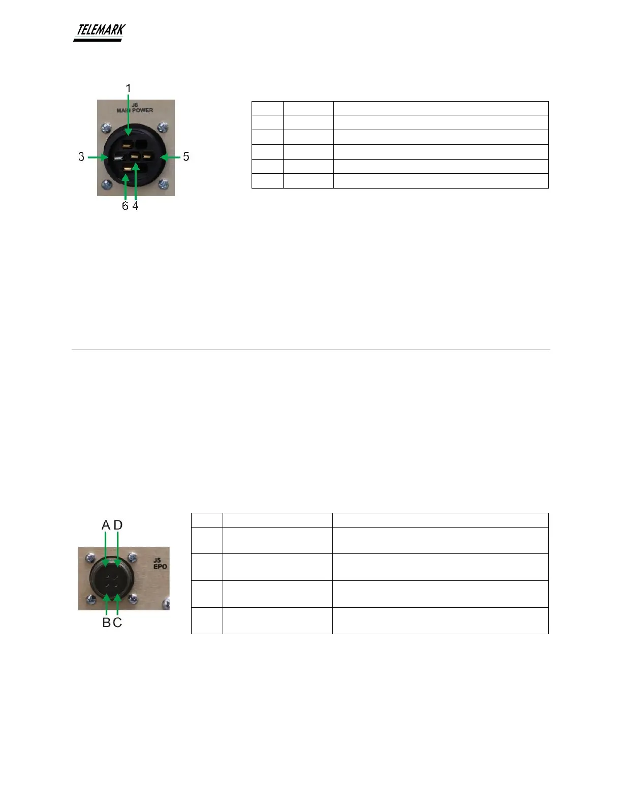
3.5.1 High Voltage Power Supply Interlock I/O
J5 – EPO – Emergency Power Off (Amphenol 4-pin M circular) leave jumpered or
connect to system EPO.
An open between pins C and D will disable the HV interlock chain and shut down HV
output.
Figure 3-10, EPO Connections
AC Ground / Physical Earth
AC Neutral, (400V models only.)
External interlock (Internally jumpered to B) Can be
used to verify Power Supply is connected.
External Interlock Return (Internally jumpered to A)
Returns signal input to Pin A.
HV interlock (+24V output from internal interlock
chain when all other interlocks satisfied.)
HV interlock Return. (Return via Jumper or dry
contact closure to satisfy HV Interlock chain.)