22 | Section 2
Each studio has an acoustic echo canceller available. The two inputs and the output are
assigned to Livewire channels on this page. The output of the AEC is labeled Backfeed because
the output of the AEC is what you usually would feed back to phones. For configuration
purposes, you should think of the AEC as a separate block outside of other VX functions. There
is no internal connection from/to the AEC and other VX signal paths.
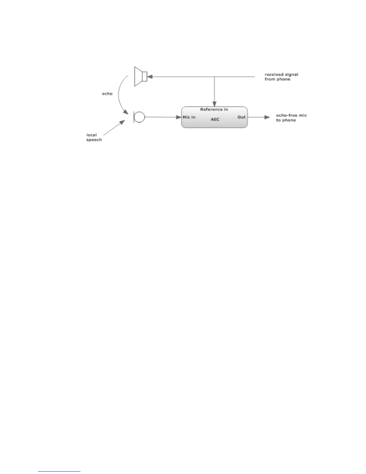
The Acoustic Echo Canceller helps with the problems that occur when you need to have loud-
speaker monitoring of calls in the same room as the microphone feeding the phone. Without
a canceller, the received caller audio would be returned to the caller as an annoying echo. (In
the old days, this acoustic coupling would more probably cause feedback howl than echo,
but today’s mobile phone and VoIP delays have made echo the trouble du jour. The canceller
needs two inputs and produces one output. The Mic input is fed from the studio microphone.
The reference input is the audio that needs to be cancelled - the received phone audio that is
going to the monitor or preview loudspeaker. The output of the canceller goes to the VX phone
feed input(s). (Why didn’t we just internally connect the canceller? Because the canceller works
best when the reference input is after anything that is in the phone-to-speaker path, such as
the volume control and mute. In a Livewire-equipped studio, it should not be too difficult to
tap the needed signals. The canceller is low-distortion and full-fidelity, so it may be used with
wideband codecs. More information on the Acoustic Echo Canceller is in Manual Section 5.
GPIO
GPIO (General Purpose Parallel Input/Output) control is possible. The Livewire channel assign-
ment for this is done on this page. The electrical connection is made via Livewire GPIO Nodes,
using the standard 5 inputs and 5 outputs per channel. You tell the system how many Livewire
channels you will use with GPIO Channel Count. After you press apply, you will see entry
fields for each of the channels. Specify the Livewire channel number you want to use for each
and choose the functions you want to assign. GPIO Actions are inputs to the VX from some
external source, which could be nothing more than a pushbutton. GPIO Indications are outputs
from the VX. For example, there’s a Ringing Line could be used for a wall-mounted lamp and
Delay dump was pressed to trigger a profanity delay unit. You can find the details regarding
the corresponding pins of the GPIO connectors in the various GPIO Node manuals.