N = 4
5 = 4
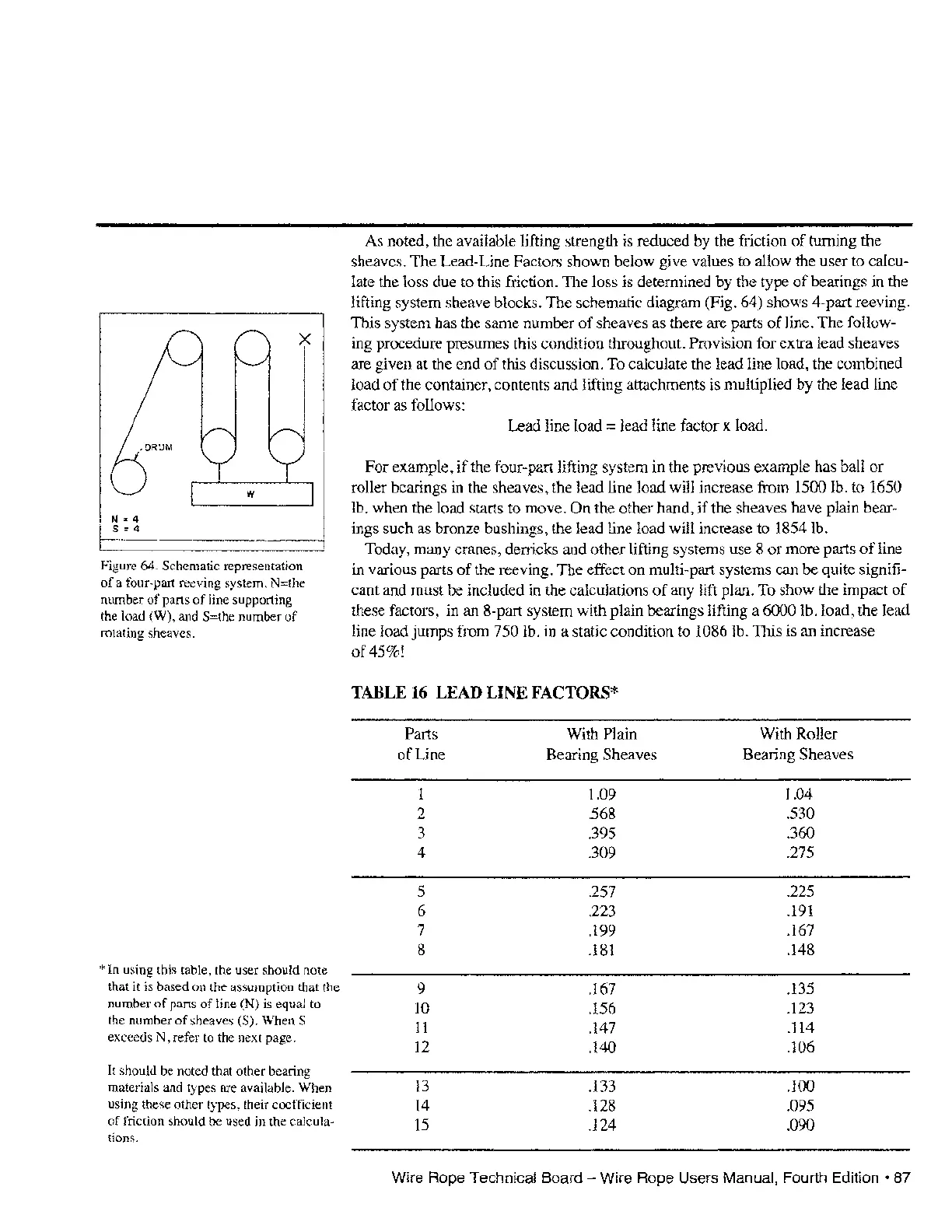
Figure 64. Schematic representation
of
a four-part reeving system, N=the
number
of
parts
of
line supporting
the load (W), and
S=the number
of
rotating sheaves.
*In
using this table, the user should note
that
it
is based on the assumption that the
number
of
parts
of
line (N) is equal to
the number
of
sheaves (S). When S
exceeds N, refer to the next page.
It should be noted that other bearing
materials and types are available. When
using these other types, their coefficient
of
friction should be used in the calcula-
tions.
As
noted, the available lifting strength is reduced by the friction
of
turning the
sheaves. The Lead-Line Factors shown below give values to allow the user to calcu-
late the loss due
to
this friction. The loss is determined by the type
of
bearings in the
lifting system sheave blocks. The schematic diagram (Fig. 64) shows 4-part reeving.
This system has the same number
of
sheaves
as
there are parts
of
line. The follow-
ing procedure presumes this condition throughout.
Provision for extra lead sheaves
are given at the end
of
this discussion.
To
calculate the lead line load, the combined
load
of
the container, contents and lifting attachments is multiplied by the lead line
factor
as
follows:
Lead line load
:=
lead line factor x load.
For example,
if
the four-part lifting system in the previous example has ball or
roller bearings
in
the sheaves, the lead line load will increase from 1500 lb. to 1650
lb. when the load starts to move. On the other hand,
if
the sheaves have plain bear-
ings such
as
bronze bushings, the lead line load will increase to 1854 lb.
Today, many cranes, denicks and other lifting systems use 8 or more parts
of
line
in various parts
of
the reeving. The effect on
mUlti-part
systems can be quite signifi-
cant and must be included in the calculations
of
any
lift plan.
To
show the impact
of
these factors, in an 8-part system with plain bearings lifting a 6000 lb. load, the lead
line load jumps from
750 lb. in a static condition to 1086 lb. This
is
an
increase
of45%!
TABLE
16
LEAD LINE FACTORS*
Parts With Plain
With Roller
of
Line Bearing Sheaves
Bearing Sheaves
1 1.09 1.04
2
.568
.530
3
.395
.360
4
.309
.275
5
.257 .225
6
.223
.191
7
.199
.167
8
.181
.148
9
.167
.135
10
.156
.123
11
.147
.114
12
.140
.106
13
.133
.100
14
.128
.095
15
.124
.090
Wire Rope Technical Board - Wire Rope Users Manual, Fourth
Edition'
87