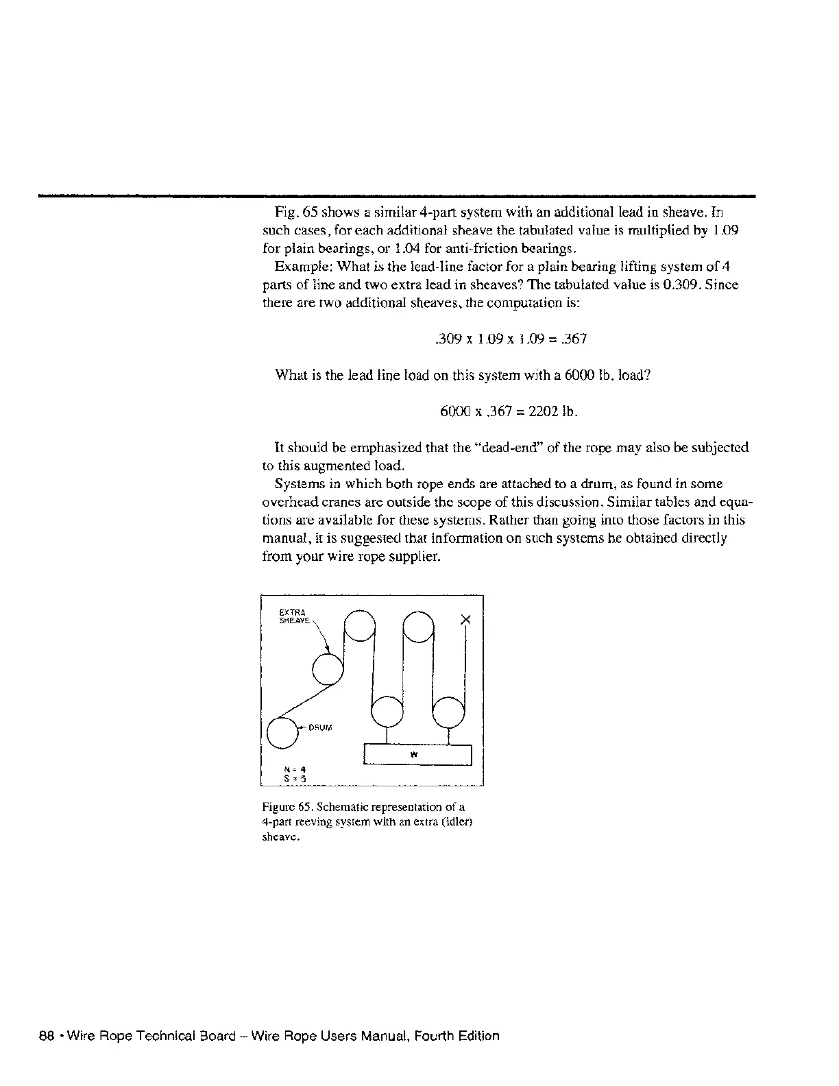
Fig. 65 shows a similar 4-part system with an additional lead in sheave. In
such cases, for each additional sheave the tabulated value is multiplied by
1.09
for plain bearings, or 1.04 for anti-friction bearings.
Example: What is the lead-line factor for a plain bearing lifting system
of
4
parts
ofline
and two extra lead in sheaves? The tabulated value is 0.309. Since
there are two additional sheaves, the computation is:
.309 x 1.09 x 1.09 = .367
What is the lead line load
on
this system with a 6000 lb. load?
6000 x .367 = 2202 lb.
It should be emphasized that the
"dead-end"
of
the rope may also be subjected
to this augmented load.
Systems in which both rope ends are attached to a drum, as found in some
overhead cranes are outside the scope
of
this discussion. Similar tables and equa-
tions are available for these systems. Rather than going into those factors in this
manual, it is suggested that information on such systems be obtained directly
from your wire rope supplier.
EXTRA
SHEAVE
N=4
5=5
Figure 65. Schematic representation
of
a
4-part reeving system with an extra (idler)
sheave.
88 • Wire Rope Technical Board - Wire Rope Users Manual, Fourth Edition