5 First steps
56
6. Click on [Ok].
7. Check assignment in the structure diagram and click on [Next
>].
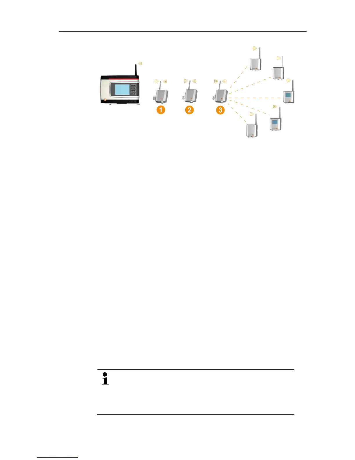
8. Place the routers in their installation locations to check the radio
connections.
9. Briefly press Connect on the back of the router that is next in
the series after the Saveris base (router 1 in the diagram).
If the LED on the front of the router flashes
• green, a radio link to the Saveris base exists.
• red, no radio link to the Saveris base exists.
10. Briefly press Connect on the back of the router that comes after
the first router in the series (router 2 in the diagram).
If the LED on the front of the router flashes
• green, a radio link to the router connected upstream of it in
the series exists.
• red, no radio link to the router connected upstream of it in
the series exists.
11. Briefly press Connect on the back of the router that comes after
the second router in the series and is therefore the furthest from
the base (router 3 in the diagram).
If the LED on the front of the router flashes
• green, a radio link to the router connected upstream of it in
the series exists.
• red, no radio link to the router connected upstream of it in
the series exists.
If no radio link exists after changing the location of the
router, introduce a converter; see "Integrating Saveris
converter (optional)".
If you want to integrate probes into the router cascade,
see Assigning probes, see Assigning probes, page 51.
 Loading...