EVM User Setup/Configuration
www.ti.com
16
SPRUIS4A–December 2019–Revised May 2020
Submit Documentation Feedback
Copyright © 2019–2020, Texas Instruments Incorporated
Jacinto7 J721E/DRA829/TDA4VM Evaluation Module (EVM)
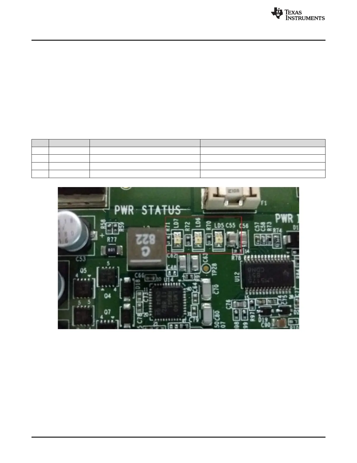
3.2.2 Power Regulators and Power Status LEDs
The processor Card utilizes an array of DC-DC converters to supply the various memories, clocks and
other components on the Card with the necessary voltage and the power required.
Dual Buck controller LM5140-Q1 provides the primary stage power conversion (12 V to 5 V / 3.3 V).
These 3.3 V and 5 V is the primary voltages for the SoM power management resources.
Buck-Boost controller LM5175 and another Buck controller LM5141 provides 12 V and 3.3 V supplies to
the expansion connectors. The power good signals of these power regulators are used to generate the
SoC PORz.
Multiple power-indication LEDs are provided on board to give users positive confirmation of the status of
output of major supplies. The LEDs indicated power in the various domains.
Table 4. Power LEDs
Sl No LED Power Status Sch Net Name
1 LD2 Input Power On/Off VINPUT
2 LD7 Regulated Power On/Off VSYS_3V3
3 LD5 SoC Main Domain On/Off VSYS_IO_3V3
4 LD6 SoC MCU Domain On/Off VSYS_MCUIO_3V3
Figure 11. Power Status LEDs