PHY ADD = 00000
Auto_neg = Enabled
ANEGsel 10/100/1000
RMGII Clock Skew TX = 0ns
RMGII Clock Skew TX = 2ns
J721E EVM Hardware Architecture
www.ti.com
50
SPRUIS4A–December 2019–Revised May 2020
Submit Documentation Feedback
Copyright © 2019–2020, Texas Instruments Incorporated
Jacinto7 J721E/DRA829/TDA4VM Evaluation Module (EVM)
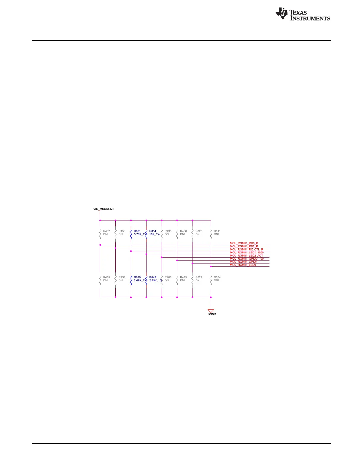
4.9.1 Gigabit Ethernet PHY Default Configuration
The default configuration of the DP83867 is determined using a number of resistor pull-up and pull-down
values on specific pins of the PHY. Depending on the values installed each of the configuration pins can
be set to one of four modes by using the pull up and pull down options provided. The EVM uses the 48-
pin QFN package, designated with the RGZ suffix, which supports only RGMII interface.
The DP83867 PHY uses four level configurations based on resistor strapping that generate four distinct
voltages ranges. The resistors are connected to the RX data and control pins that are normally driven by
the PHY and are inputs to the processor. The voltage range for each mode is shown below:
• Mode 1 - 0V to 0.3V
• Mode 2 – 0.462 V to 0.6303 V
• Mode 3 – 0.7425 V to 0.9372 V
• Mode 4 – 2.2902 V to 2.9304 V
These are the defaults set for the MCU RGMII.
• PHY ADDR: 00000
• Auto_neg: Enabled
• ANGsel 10/100/1000
• RGMII Clk skew Tx: 0 ns
• RGMII Clk skew Rx: 2 ns
The strapping resistors are shown in Figure 31.
Figure 31. MCU Ethernet PHY Settings