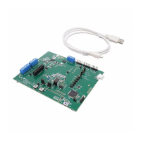
Figure 4-5. TPS25751EVM and BQ25713EVM Hardware Setup..............................................................................................28
Figure 4-6. Liquid Detection/Corrosion Mitigation Setup........................................................................................................... 30
Figure 4-7. Liquid Detection Resistor Selection.........................................................................................................................31
Figure 4-8. Liquid Detection Resistor Location..........................................................................................................................31
Figure 5-1. TPS25730 Power Input Schematic......................................................................................................................... 33
Figure 5-2. Type-C Connectors Schematic................................................................................................................................34
Figure 5-3. Power Stage Schematic.......................................................................................................................................... 35
Figure 5-4. TPS25751 Schematic..............................................................................................................................................36
Figure 5-5. Liquid Detection Schematic.....................................................................................................................................37
Figure 5-6. TIVA Schematic....................................................................................................................................................... 38
Figure 5-7. TPS25751EVM Top Layer Composite View............................................................................................................39
Figure 5-8. TPS25751EVM Bottom Layer Composite View...................................................................................................... 39
Figure 5-9. TPS25751EVM Ground Layer.................................................................................................................................40
Figure 5-10. TPS25751EVM Signal Layer.................................................................................................................................40
Figure 5-11. TPS25751EVM Power1 Layer...............................................................................................................................41
Figure 5-12. TPS25751EVM Power 2 Layer............................................................................................................................. 41
Figure 5-13. TPS25751EVM Board Dimensions....................................................................................................................... 42
List of Tables
Table 1-1. Devices on TPS25751EVM........................................................................................................................................ 4
Table 2-1. J6 Header Pinout........................................................................................................................................................ 6
Table 2-2. Jumper Descriptions .................................................................................................................................................. 7
Table 2-3. LEDs........................................................................................................................................................................... 8
Table 2-4. Test Points.................................................................................................................................................................. 8
Table 2-5. Switches/Push Buttons............................................................................................................................................... 8
Table 3-1. TPS25751 Configuration...........................................................................................................................................11
Table 4-1. TPS25751EVM and BQ25792/8EVM Connections.................................................................................................. 26
Table 4-2. TPS25751EVM and BQ25713EVM Connections..................................................................................................... 28
Table 4-3. Liquid Detection Test Points......................................................................................................................................32
Table 4-4. Liquid Detection/Corrosion Mitigation Default Configuration.................................................................................... 32
Table 5-1. Bill of Materials .........................................................................................................................................................43
www.ti.com Table of Contents
SLVUCP9A – NOVEMBER 2023 – REVISED MARCH 2024
Submit Document Feedback
TPS25751 Evaluation Module 3
Copyright © 2024 Texas Instruments Incorporated
 Loading...


