EX-TRAFIRE
®
105HD 4 Product description
11
4 Product description
4.1 Assembly and use
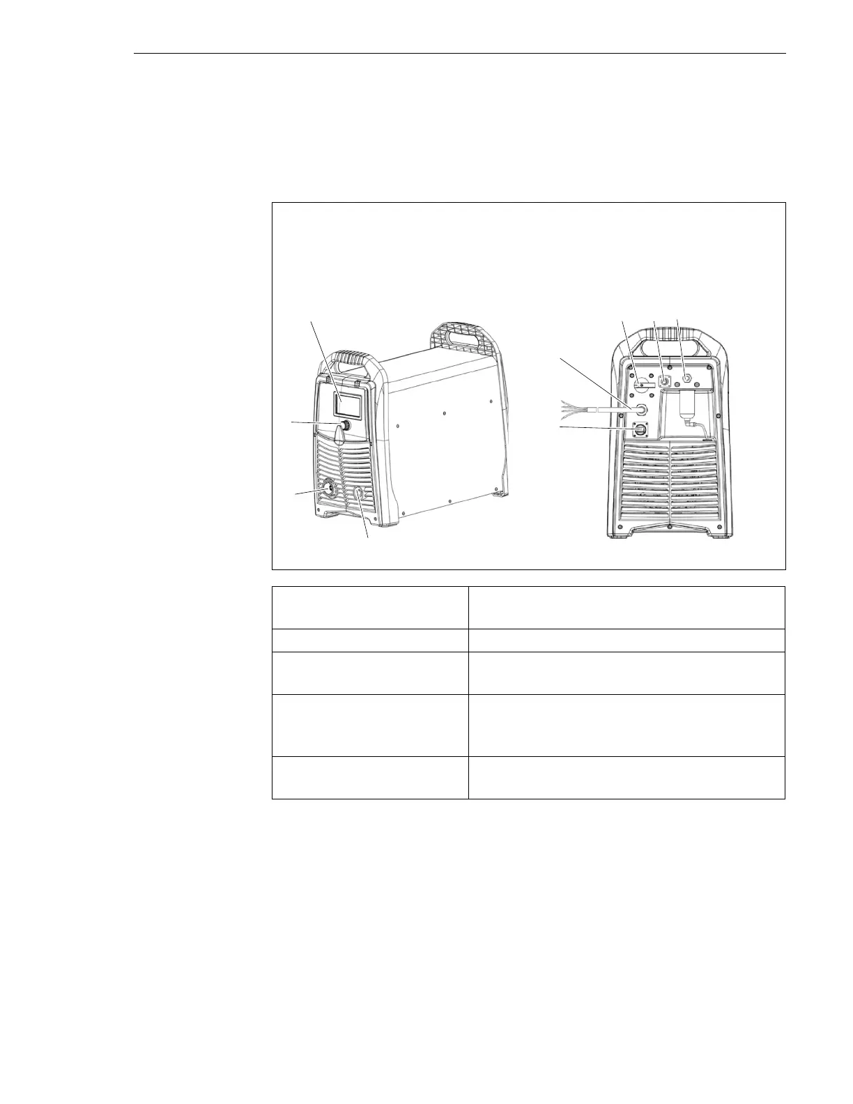
The control elements are located on the control panel. The connections are
on the front and rear of the power supply.
Fig. 2 Control elements and connections
A LCD Display
B POWER switch
C Optional BUS interface
D G 1/4" gas connection, plug
E Optional CNC interface
F Power cable
G Work lead connection
H Torch connection system (TCS)
I Multi-function button
LCD display (A) Displays the status of the power supply. A
fault code is displayed if an error occurs.
POWER switch (B) Used to switch the power supply on and off.
Optional BUS interface (C) For the connection of the optional CAN BUS
or RS485/422 BUS.
Optional CNC interface
connection (E)
This optional interface is used to connect the
power supply to an optional CNC cutting
table or robot.
Multi-function button (I) For toggling between two menus and
setting the cutting parameters.