EX-TRAFIRE
®
105HD 21 Appendix
67
21 Appendix
21.1 Connecting the optional CNC interface
The optional CNC interface plug installs onto the rear panel of the
EX-TRAFIRE
®
105HD. Control signals can be transmitted via the CNC
interface. For signal types see table 27. Control elements are located on
the control panel. Connections are on the front and rear of the power
supply.
4.1 Assembly and use on page 11
Electric shock due to live parts
Live parts are exposed when the housing is open. This can result in fatal
electric shock.
Set the POWER switch to OFF and disconnect the input power plug
before opening the housing.
Use Lock-out/Tag-out according to local regulations.
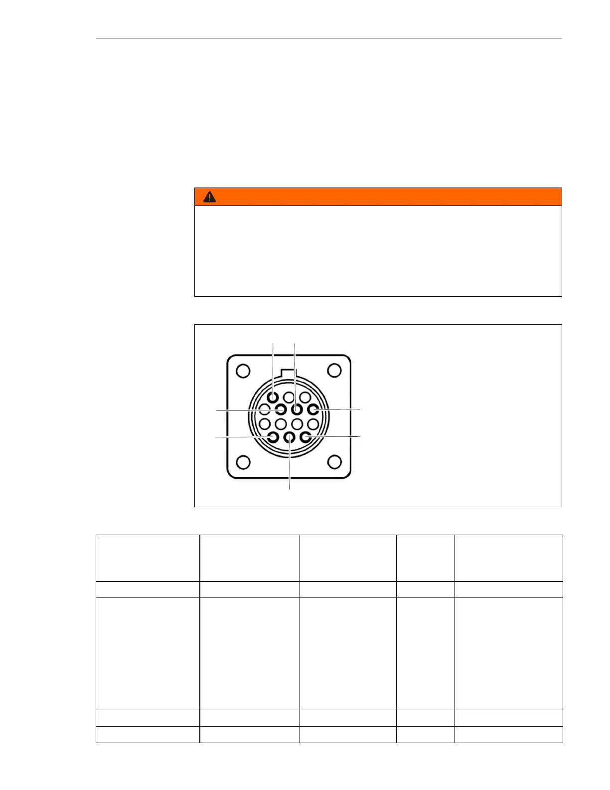
Fig. 10 Signal and pin assignment for CNC interface
Table 27 Signal and pin assignment
Signal START
Start plasma
cutting
Arc
Start machine
motion
Ground Voltage divider
Type Input Output Ground Output
Notice Open by default.
Requires potential-
free contact to
close.
Open by default.
Potential-free with
max. capacity of:
120 V AC/1 A
Reduced arc signal:
20:1
21.1:1
30:1
40:1
50:1
(supplies max. 18 V)
PIN 3, 4 12, 14 13 6 (+), 5 (−)
Internal cable color White, white Yellow, yellow Green 6 (red), 5 (black)