8. Refer to Figure 5-5 for the next steps. Remove the nylon screws along
the right side of the cabinet. Remove the outer door hinges. Rotate
them 180° and install them on the right side of the cabinet. Install the
nylon screws in the holes vacated by the hinges.
9. With a 1/8” Allen wrench, remove the door open switch target plate
on the top of the inner door.
10. Remove the door latch striker plate.
11. Hold the door securely and remove the upper hinge bracket on the
cabinet. This hinge bracket will be rotated 180° and be placed in the
lower right corner of the cabinet where indicated.
12. Lift the glass door from the lower hinge and set it aside. Then remove
the lower hinge from the cabinet. This hinge bracket will be rotated
180° and be placed in the upper right corner of the cabinet at where
indicated.
13. Remove the screws and washers from the new striker plate location.
These screws and washers can be threaded into the holes vacated by the
striker plate where indicated.
14. Rotate the striker plate 180° from its original position and attach it to
the cabinet where indicated.
15. Using a flatblade screwdriver, remove the threaded nylon plugs from
the new hinge bracket locations. Install the lower hinge bracket where
indicated.
5-6 Model 310 Series DH Incubator Thermo Scientific
Section 5
Routine Maintenance
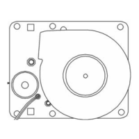
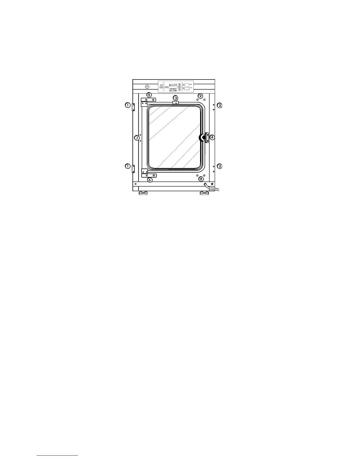
Figure 5-5. Component Locations
Reversing the Door
Swing (continued)