TH2827 Series Operation Manual Chapter 5 Execute LCR Operation and Some Examples
60
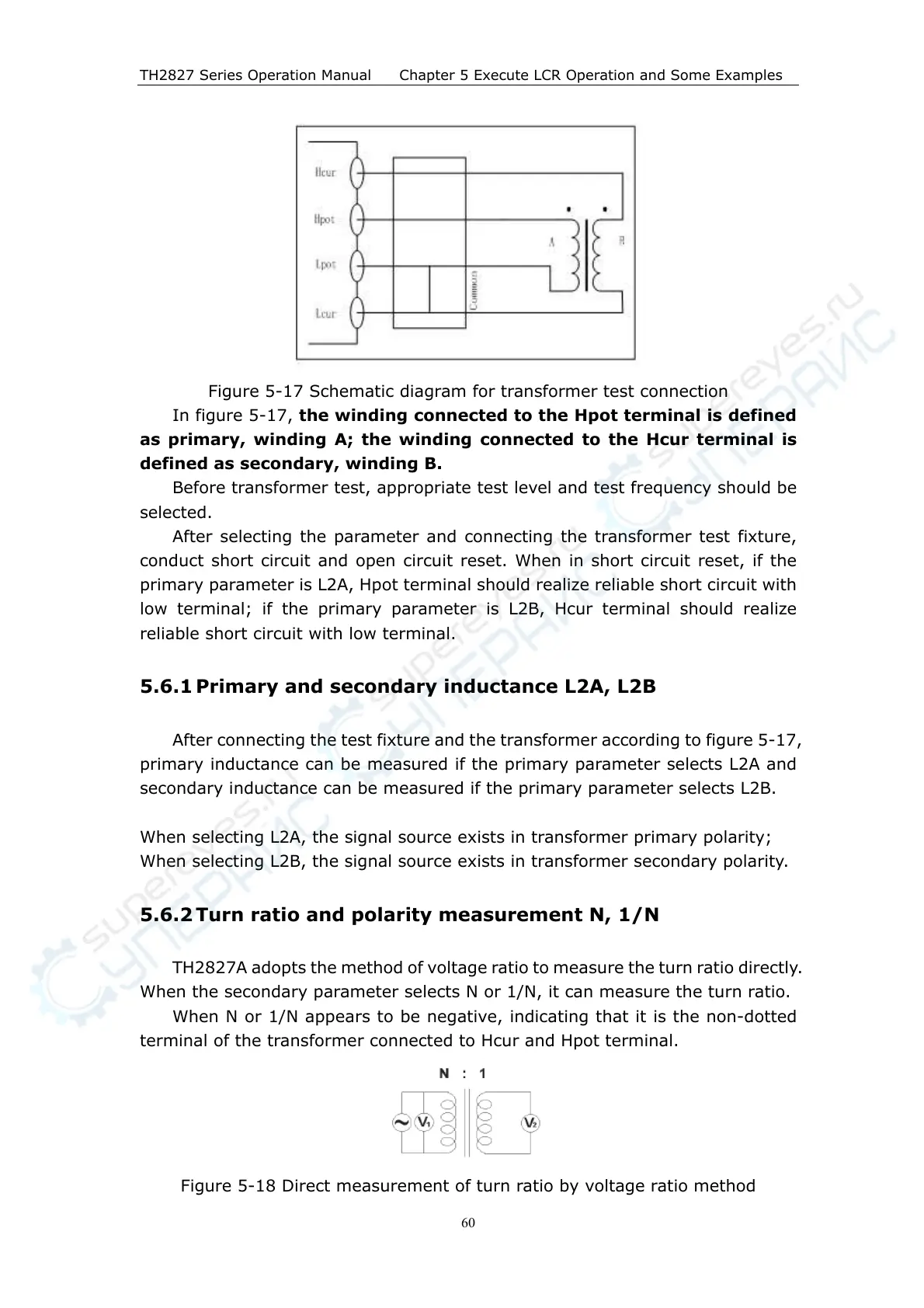
Figure 5-17 Schematic diagram for transformer test connection
In figure 5-17, the winding connected to the Hpot terminal is defined
as primary, winding A; the winding connected to the Hcur terminal is
defined as secondary, winding B.
Before transformer test, appropriate test level and test frequency should be
selected.
After selecting the parameter and connecting the transformer test fixture,
conduct short circuit and open circuit reset. When in short circuit reset, if the
primary parameter is L2A, Hpot terminal should realize reliable short circuit with
low terminal; if the primary parameter is L2B, Hcur terminal should realize
reliable short circuit with low terminal.
5.6.1 Primary and secondary inductance L2A, L2B
After connecting the test fixture and the transformer according to figure 5-17,
primary inductance can be measured if the primary parameter selects L2A and
secondary inductance can be measured if the primary parameter selects L2B.
When selecting L2A, the signal source exists in transformer primary polarity;
When selecting L2B, the signal source exists in transformer secondary polarity.
5.6.2 Turn ratio and polarity measurement N, 1/N
TH2827A adopts the method of voltage ratio to measure the turn ratio directly.
When the secondary parameter selects N or 1/N, it can measure the turn ratio.
When N or 1/N appears to be negative, indicating that it is the non-dotted
terminal of the transformer connected to Hcur and Hpot terminal.
Figure 5-18 Direct measurement of turn ratio by voltage ratio method