MINTER Configuration
P/N 7010-0816
3-17
Once the receiver is configured, the configuration remains until
you change it using PC-CDU/TopSURV/Pocket-3D or clearing
the NVRAM.
For more details on the settings available for configuring the Base
and Rover receivers, refer to the PC-CDU Reference Manual.
14. Continue with other configuration activities or click File
Disconnect, and then FileExit to quit PC-CDU. Disconnecting
before exiting ensures proper port management.
MINTER Configuration
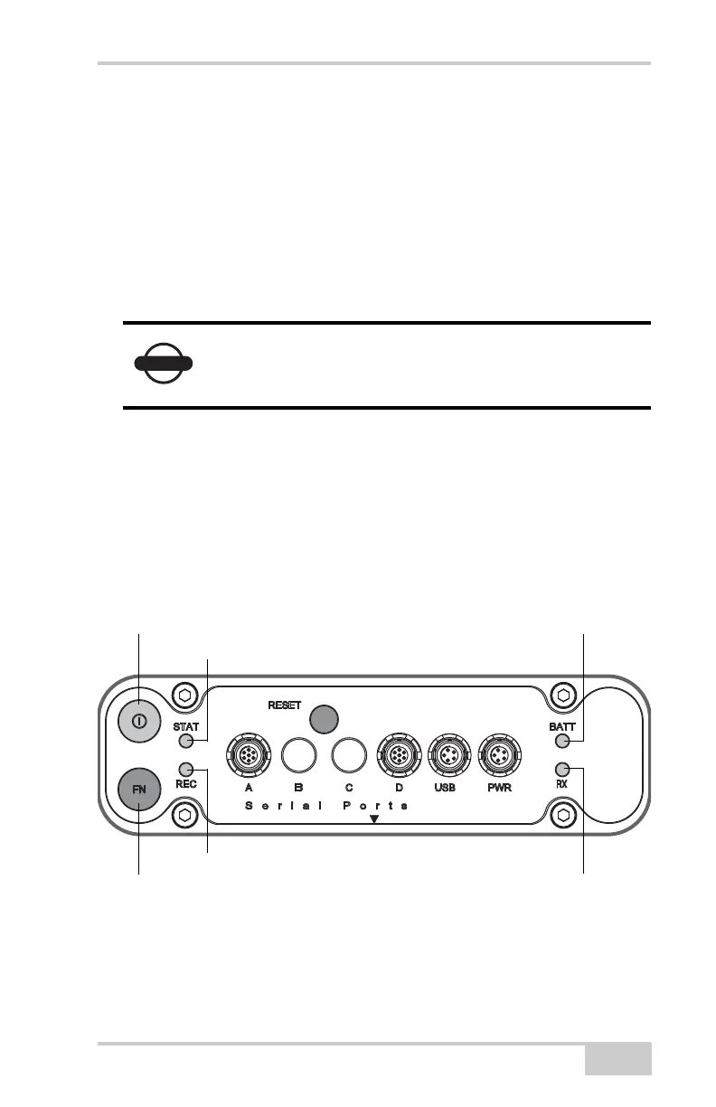
The Minimum INTERface (MINTER) consists of two keys (Power
and FN) that control the receiver’s operation, four LEDs (STAT, REC,
BATT, and RX) that display the receiver’s operational status, and two
LEDs that display the battery status (Figure 3-14).
Figure 3-14. MINTER
The MINTER performs the following functions. For more
information on using the MINTER, see “MINTER Operation” on
Disconnect the receiver from PC-CDU before
exiting to eliminate possible conflicts with the
management of the computer’s serial ports.
Power Key
FN Key
Battery LED
Modem Status
LED
Status LED
Record LED

 Loading...