Operation
Motorgrader System Five Operator’s Manual
2-2
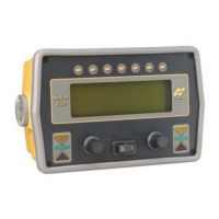
Control Box Front Panel Switches
and Controls
The operator can control and monitor grading using the switches and
displays located on the front panel of the Control Box. The function
of each is as follows:
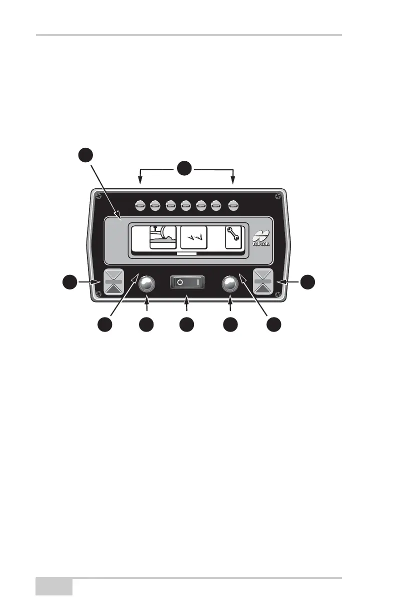
Figure 2-1.
1. LCD Display
2. Left and Right Grade Adjustment LED's
3. Left and Right Automatic
Operation Indicators
4. Left and Right Grade
Adjustment Knob
5. Power Switch
6. Function Buttons
System
Five
System
Five
A
u
t
o
A
u
t
o
MAIN MENU
3D
-
M
CC
ont
r
ol
S
e
tup
3
D
1
2
3
4 5
6
3
4
2